Assembly and method for forming a seal in a junction of a multilateral well bore

a multi-lateral well and junction technology, applied in the direction of directional drilling, borehole/well accessories, construction, etc., can solve the problems of limited completion options, inability to use current technology, and primary barriers to the increased use of multi-lateral technology, so as to prevent the migration of fluids, prevent the effect of migration and cost saving

Inactive Publication Date: 2001-04-03
WEATHERFORD TECH HLDG LLC
View PDF5 Cites 135 Cited by
  • Summary
  • Abstract
  • Description
  • Claims
  • Application Information

AI Technical Summary

Benefits of technology

Also a further object of this invention is to provide a compression sealing member for creation of a seal between the tubular sleeve member in the main well bore casing and the tubular member, or production liner in some cases, in order to prevent the migration of fluids either into or out of the main well bore casing or tubular member.
Yet a further object of this invention is to provide a compression sealing member for receiving sufficient fluid to expand the compression sealing member to create a seal between the compression sealing member and the tubular sleeve member in the main well bore casing in order to prevent the migration of fluids wither into or out of the main well bore casing or tubular member, which may be a production liner.
A further object of this invention is to provide a sealing member for seating with the a seating surface inside the tubular sleeve member proximate the aperture through the one side of the tubular sleeve member, and moved into engagement with the seating surface for preventing the migration of fluids either into or out of the main casing o

Problems solved by technology

For example in completions systems and technology for the installation of lateral junctions in certain formations which are well known, there has been a primary barrier to the increased use of multilateral technology.
This barrier has been the limitations in the completion options available, particularly in those situations in which a sealed junction is required to effectively produce a reservoir.
These are just some of the situations which the current technology has not been able to over come on a consistent basis, except with the most expensive technologies in use today.
Further the technology which has only recently become available for the formation of junctions with hydraulic integrity is often too expensive to allow its utilization in all but the large budget wells, such as those found in offshore locations.
At the present time, this sealed completion technology is generally not accepted as reliable by the industry for the average budget well.
This has resulted in potentially high economic risk to install such systems.
In addition, these completion systems may not allow the capability to selectively re-enter these laterals at a future time, nor to pressure test the junction for hydraulic integrity prior to the removal of the installation tools.
The prior art until the mid-1990's did not typically have a liner laid in a lateral and therefore these laterals were not tied back to the main well bore which severely limited or made impossible the re-entry of these laterals when workovers or cleanouts were required.
However, subsequently, it became increasingly popular to case the laterals, as well as t

Method used


Image

  • Assembly and method for forming a seal in a junction of a multilateral well bore
  • Assembly and method for forming a seal in a junction of a multilateral well bore
  • Assembly and method for forming a seal in a junction of a multilateral well bore

Examples


Embodiment Construction

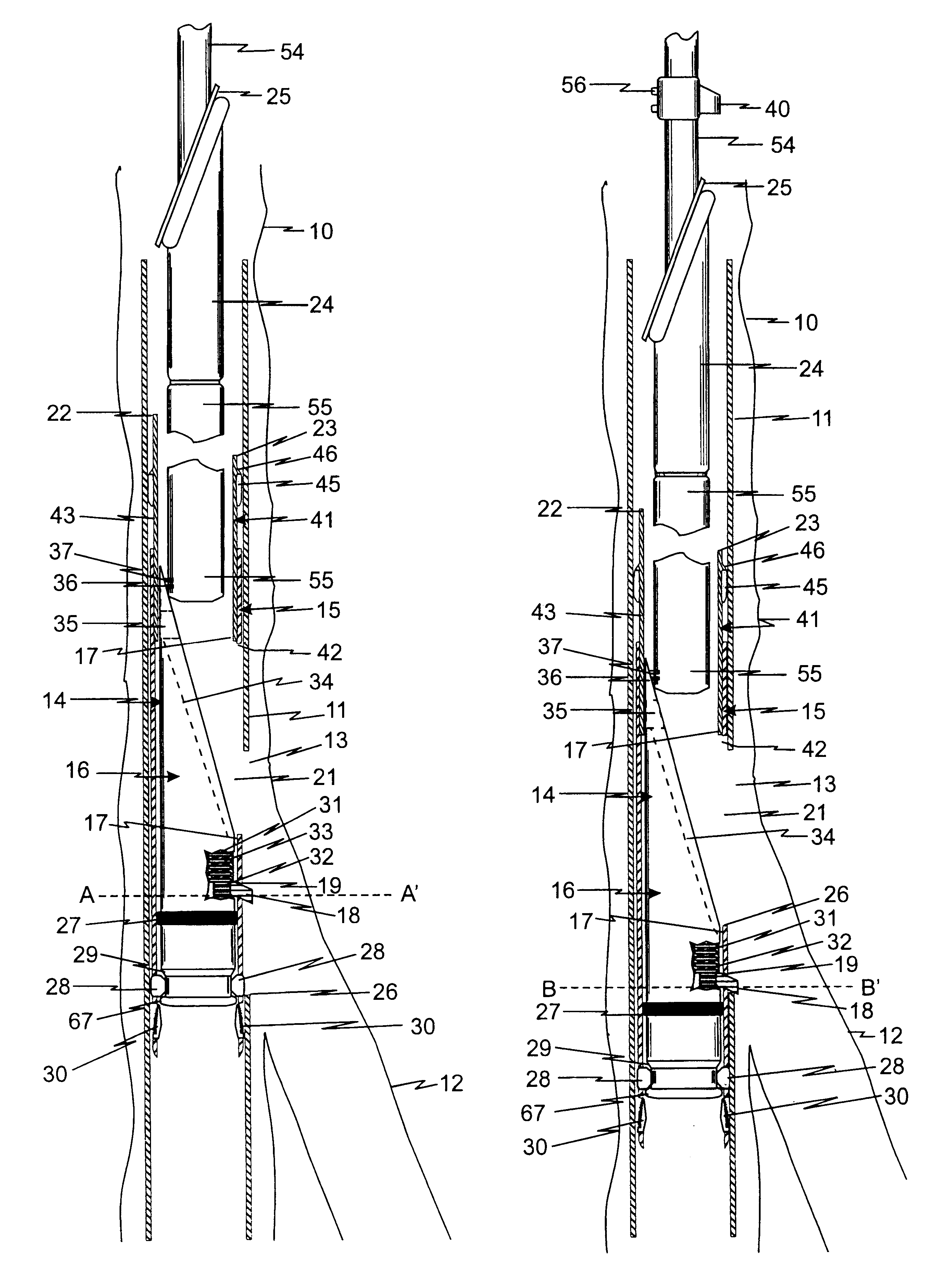
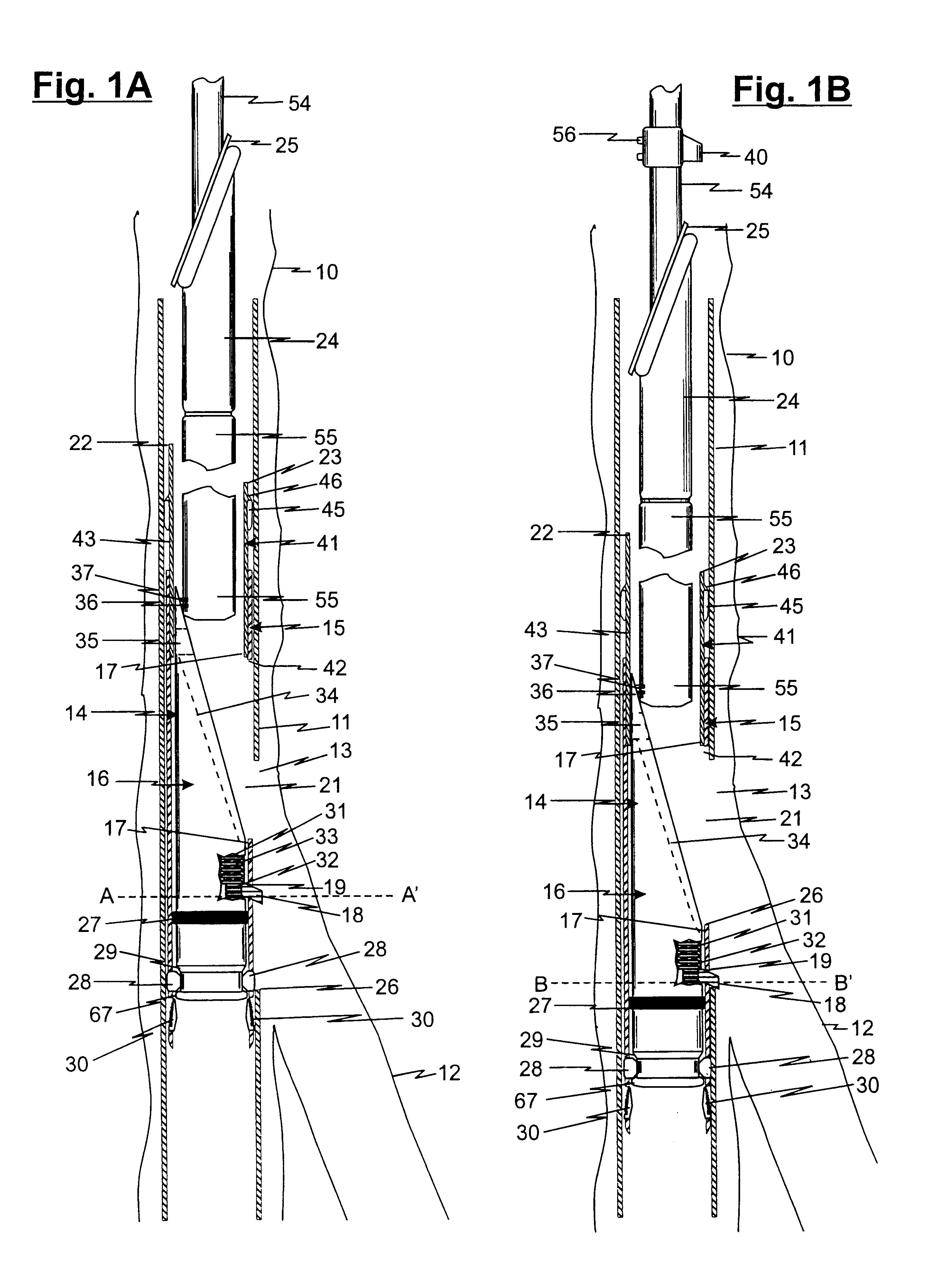
Referring now to FIG. 1A wherein a representational main well bore is generally shown as with a main well bore casing shown at 11, it should be understood all through out the teachings of this invention that while the drawings and discussion about the preferred embodiments may refer to vertical for the main well bore 10 or main well bore casing 11, they, in fact, may be in a vertical position, or deviated therefrom, or a horizontal position, without departing from the teachings of this invention. Further it should be understood that the references to up hole and down hole as shown in the drawings and discussions about the preferred embodiment, may, in fact, in the ground be horizontal on occasions or even have up hole and down hole reversed, but the general teaching is that up hole mean back toward the surface of the ground and downhole means into the hole in the opposite direction from up hole whether it is down hole or not in the well. Similarly the term lateral well bore or a mul...


PUM


Abstract

This invention relates to an assembly and method for forming a hydraulic seal at the junction of a multilateral well bore drilled through a window in at least a main well bore comprising a tubular member which is run into the well bore casing and has a sealing member positioned about the tubular member for seating, at least one orientation member being provided for orientation of the tubular member and sealing member in the main well bore casing, and having a tubular sleeve member for insertion in the well bore which has an aperture through at least one side of the tubular sleeve member for alignment of the aperture with the window and having a seating surface on the inside of the tubular sleeve member proximate the aperture, with the aperture in some embodiments being adjustable, and having a deflection member positioned and releasable sealed in the tubular sleeve member for deflecting the tubular member through the window in the well bore when the tubular member is run into contact with the deflection member, and having at least one orientation member for orientation of the deflection member relative to the window in the at least well bore casing and for aligning the aperture in the tubular sleeve with the window and a method of using the assembly to form a seal at the junction which can be executed in one run into the well bore casing in at least one embodiment.

Description

This invention relates to an assembly and method to be used in the formation of seals at the junction of lateral wells drilled through windows in a main well bore casing or through any tubular type materials. Specifically this invention relates to novel and improved assemblies and methods used for forming seals in any deviated well bore which is drilled off or from another well bore whether it is vertical, deviated or horizontal and whether it is the primary well bore casing or other tubular material. More specifically this invention relates to the completion procedures used in completion of wells with deviated well bores off a main or casing well bore where as part of the completion procedure the well may be cemented and sealed.The drilling and completion of horizontal wells in recent years has offered dramatic improvements in the production of hydrocarbons and their recovery from the formations in which they are found. Although horizontal wells have been known for many years, it h...

Claims


Application Information

Patent Timeline
IPC IPC(8): E21B41/00E21B7/08
CPCE21B41/0042
Inventor BRUNET, CHARLES G.
Owner WEATHERFORD TECH HLDG LLC
Why Eureka
Try Eureka