Optical filtering system for a laser bar code scanner having narrow band-pass characteristics employing spatially separated filtering elements including a scanner window

a laser bar code scanner and optical filtering technology, applied in the field of laser scanners, can solve the problems of difficult and expensive manufacture of the optical filter element of the relatively small second optical filter elemen

Inactive Publication Date: 2001-04-03
METROLOGIC INSTR
View PDF18 Cites 281 Cited by
  • Summary
  • Abstract
  • Description
  • Claims
  • Application Information

AI Technical Summary

Benefits of technology

Accordingly, it is a primary object of the present invention to provide a laser bar code symbol scanning system that is capable of reading bar code symbols, without the shortcomings and drawbacks of prior art devices.
A further object of the present invention is to provide a laser bar code symbol scanner having a novel optical filtering system which provides improved scanner performance, appearance and manufacturability.
A further object of the present invention is to provide such a laser bar code symbol scanner, in which the wavelength-selective components of the optical filter system are strategically installed in a spatially-separated manner in order to achieve improved scanner performance, appearance and manufacturability, in a simple low-cost manner.
A further object of the present invention is to provide a laser bar code symbol scanner that satisfies the concerns of store owners and managers alike, while effectively overcoming the problems caused by high intensity ambient lighting.

Problems solved by technology

As a result of this novel laser scanner construction, the wavelength selective properties of the first optical filter element inherently render it semi-transparent, and thus hide from plain view, otherwise aesthetically unappealing electro-optical components mounted within the scanner housing.
Whereas the optical filtering properties of the relatively large first optical filter element render its manufacture relatively easy and inexpensive, the optical filtering properties of the relatively small second optical filter element render its manufacture relatively difficult and expensive.

Method used


Image

  • Optical filtering system for a laser bar code scanner having narrow band-pass characteristics employing spatially separated filtering elements including a scanner window
  • Optical filtering system for a laser bar code scanner having narrow band-pass characteristics employing spatially separated filtering elements including a scanner window
  • Optical filtering system for a laser bar code scanner having narrow band-pass characteristics employing spatially separated filtering elements including a scanner window

Examples


Embodiment Construction

For purposes of illustration, the present invention will be described below with reference to the accompanying Drawings, with like structures being indicated by like reference numbers.

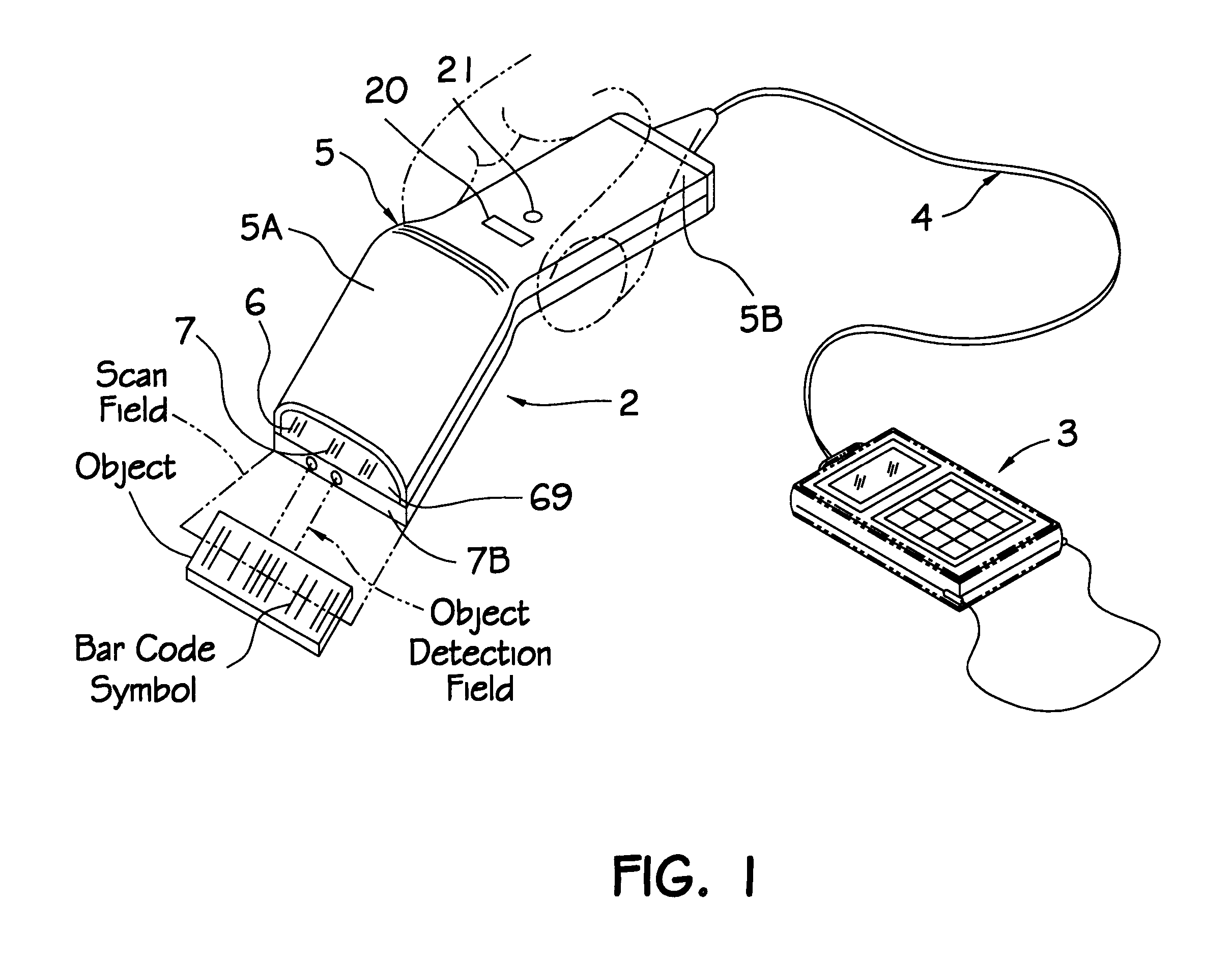
As shown in FIG. 1, automatic bar code symbol reading system 1 of the first illustrative embodiment comprises an automatic hand-holdable bar code symbol reading device 2 operably associated with hand-holdable data collection device 3, described in detail in U.S. Pat. No. 5,340,971. Operable interconnection of bar code symbol reading device 2 and data collection device 3 is achieved by a flexible multiwire connector cord 4 extending from bar code symbol device 2 and plugged directly into the data-input communications port of the data collection device 3.

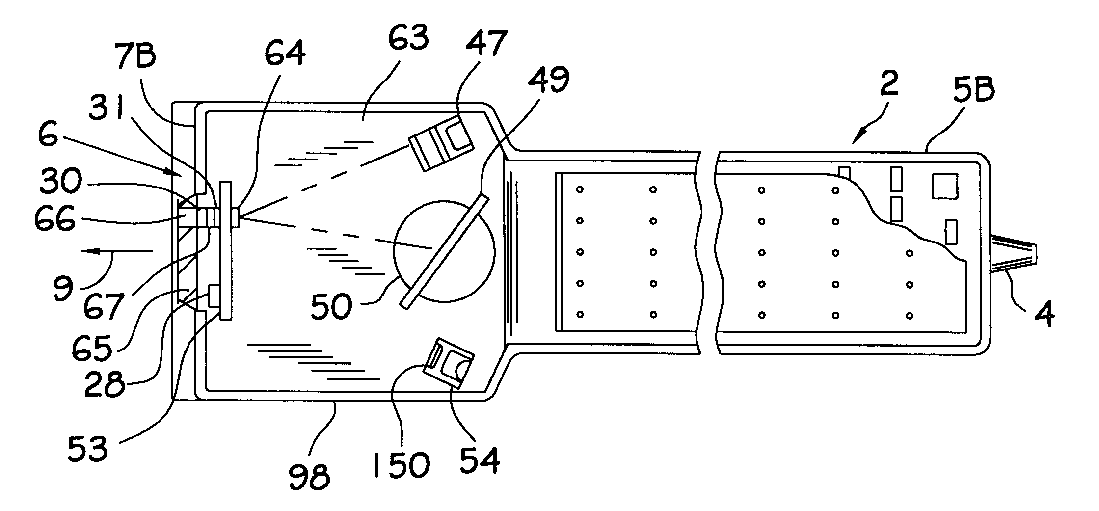
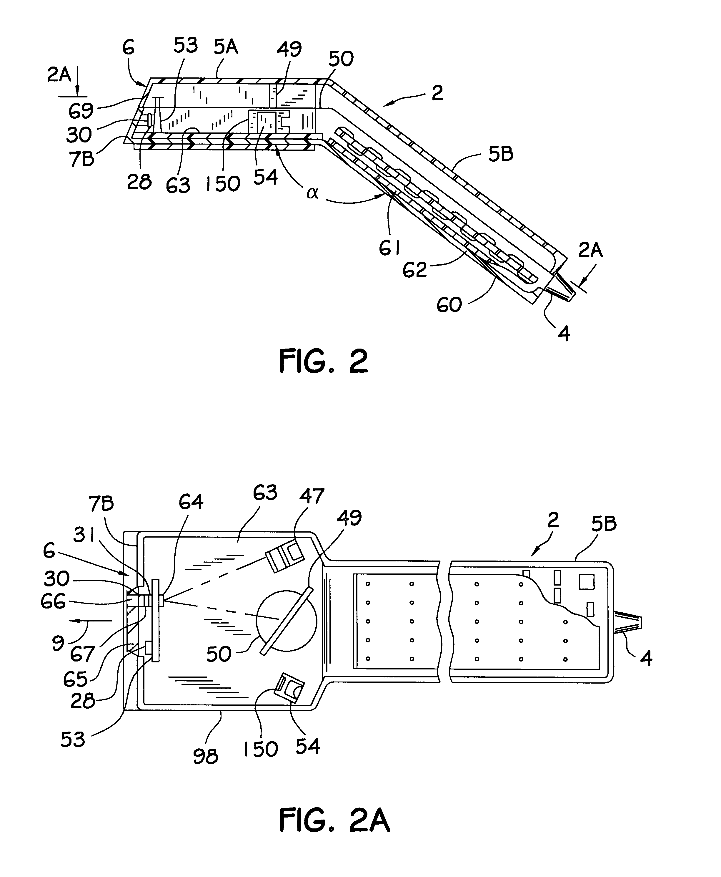
Referring to FIGS. 1 through 2A, automatic bar code symbol reading device 2 is shown to comprise an ultra-lightweight hand-holdable housing 5 having a head portion 5A that continuously extends into a contoured handle portion 5B. As illustrated in FIGS. 1...


PUM


Abstract

A novel optical filtering system for a laser bar code scanner having narrow band-pass characteristics is disclosed. The optical filtering system has two different optical filtering elements which are disposed in a scanner housing in a spatially separate relationship. One of the optical filtering elements is positioned inside of the scanner housing in front of and close to the light detection element. The other optical filtering element is positioned in the light transmission aperture of the scanner housing and forms the scanning window. The optical filtering characteristics of the scanning window obscure the internal components of the scanner from plain view making the scanner appear more aesthetically pleasing. Together the optical filtering element cooperate to form a narrow-band pass filter to provide for better light collection and scanning.

Description

1. Field of the InventionThe present invention relates generally to laser scanners used in reading bar and like code symbols, and more particularly to a novel optical filtering system for use therein, which provides improved scanner performance, appearance and manufacturability at lower cost.2. Brief Description of the Prior ArtLaser-based bar code symbol scanning systems have become increasingly popular in recent times. However, despite technical advancements in the art, such systems still suffer from numerous problems that have yet to be adequately solved.For example, a major problem with prior art laser scanners is that as they become more widely used in point-of-sale (POS) environments, aesthetic considerations play a greater role in their purchase decisions by store managers considering their use at POS locations. The reason for this is clear. Store owners invest in a great deal of time, money and artistic effort in making their stores and display counters attractive to custome...

Claims


Application Information

Patent Timeline
Patent Type & Authority Patents(United States)
IPC IPC(8): G02B26/10G06K17/00G06K7/14G06K7/10
CPCG02B26/106G06K7/10564G06K7/10594G06K7/10603G06K7/10663G06K7/10693G06K7/10702G06K7/10792G06K7/10801G06K7/10851G06K7/10861G06K7/10881G06K7/10891G06K7/14G06K7/1443G06K17/0022G06K2207/1012G06K2207/1016G06K2207/1017G06K2207/1018
Inventor AMUNDSEN, THOMASBLAKE, ROBERTROCKSTEIN, GEORGEWILZ, SR., DAVID M.KNOWLES, CARL H.
Owner METROLOGIC INSTR
Why Eureka
Try Eureka