Polypropylene filler rods for optical fiber communications cables

a technology of polypropylene and filler rods, applied in the field of communication cables, can solve the problems of reducing crush resistance, reducing the ease of cable and fiber access, and excessive post extrusion shrinkag

Inactive Publication Date: 2001-04-03
DRAKA COMTEQ BV
View PDF5 Cites 207 Cited by
  • Summary
  • Abstract
  • Description
  • Claims
  • Application Information

AI Technical Summary

Problems solved by technology

However, some problems experienced with filler rods made from such material in some environments in which cables containing such rods includes excessive post extrusion shrinkage and reduced crush resistance, especially in low count cables with many filler rods.
When this happens, the filler rods can stick to the outer jacket, a phenomenon which is undesirable because it decreases the ease of cable and fiber accessibility.

Method used


Image

  • Polypropylene filler rods for optical fiber communications cables
  • Polypropylene filler rods for optical fiber communications cables
  • Polypropylene filler rods for optical fiber communications cables

Examples


Embodiment Construction

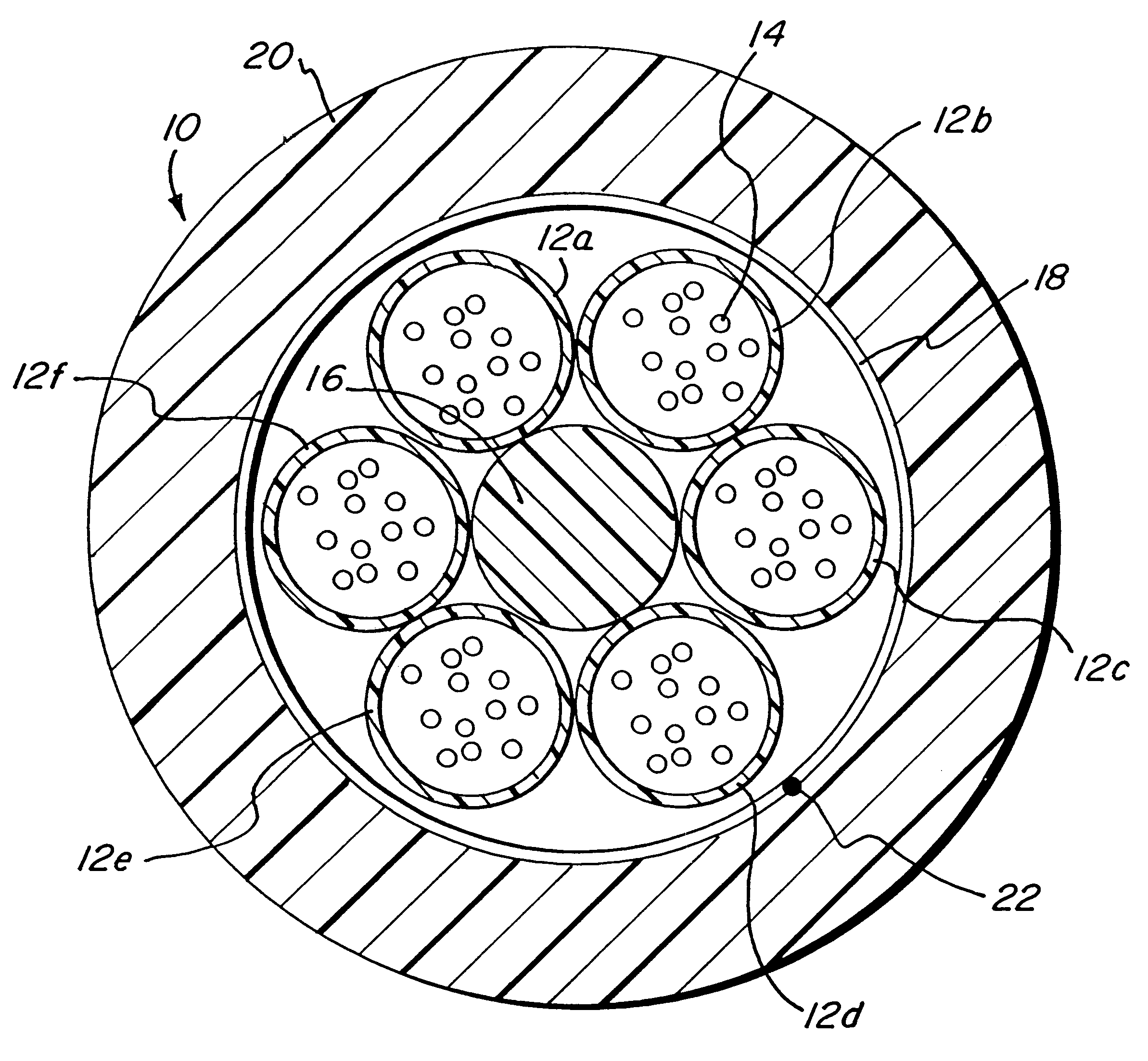
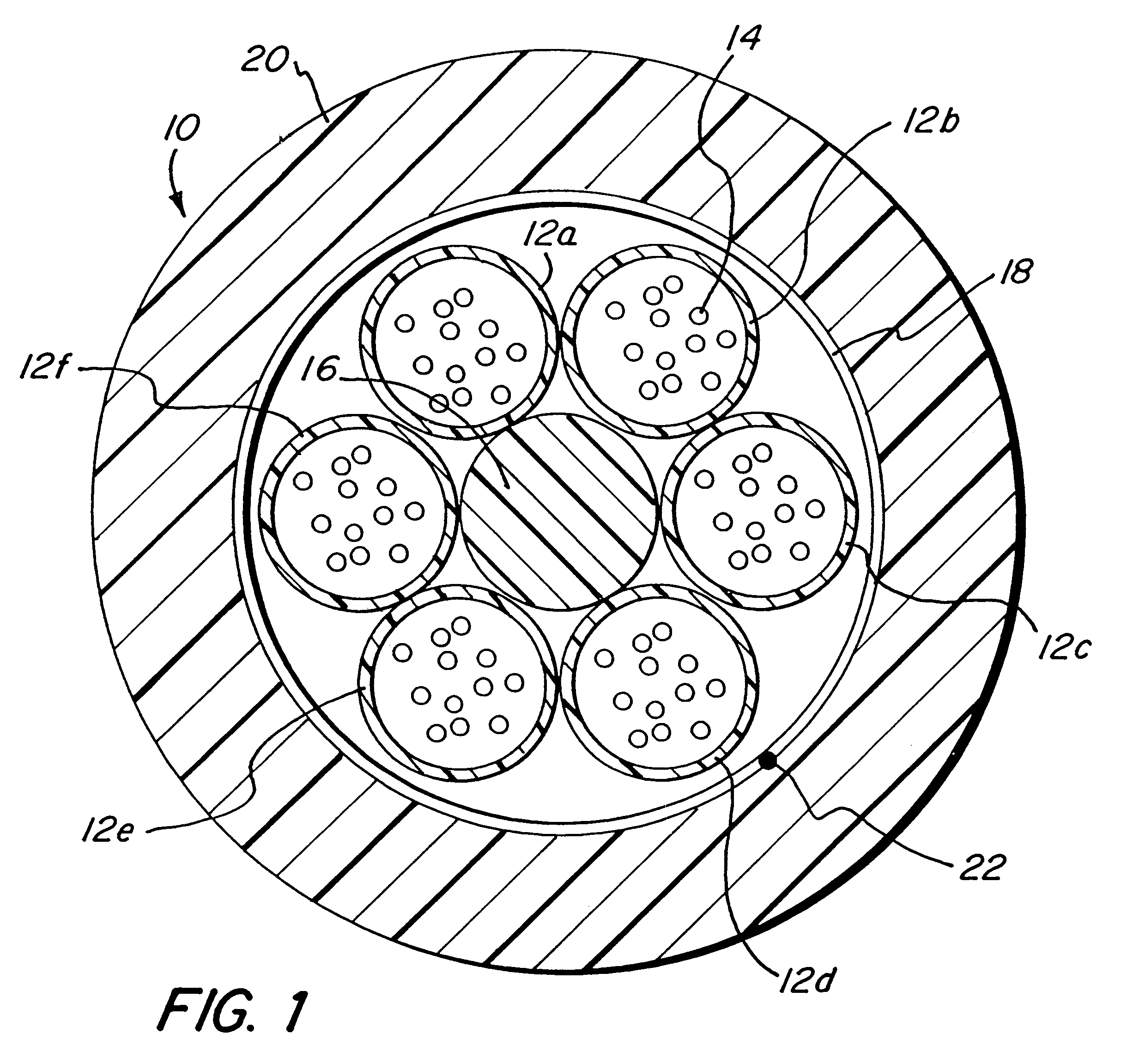
FIG. 1 illustrates a typical stranded optical fiber cable. The cable 10 has a core comprised of a plurality of buffer tubes 12a-12f, each of which house optical fibers 14, stranded about a central strength member 16. A core wrap 18 may positioned over the core. Water blocking materials (not shown) may be disposed in the core, if desired. A protective outer jacket 20 is disposed over the core and a ripcord 22 is provided near the interface of the wrap 18 and the outer jacket 20. The cable 10 illustrated in FIG. 1 has a maximum fiber count of 72 fibers.

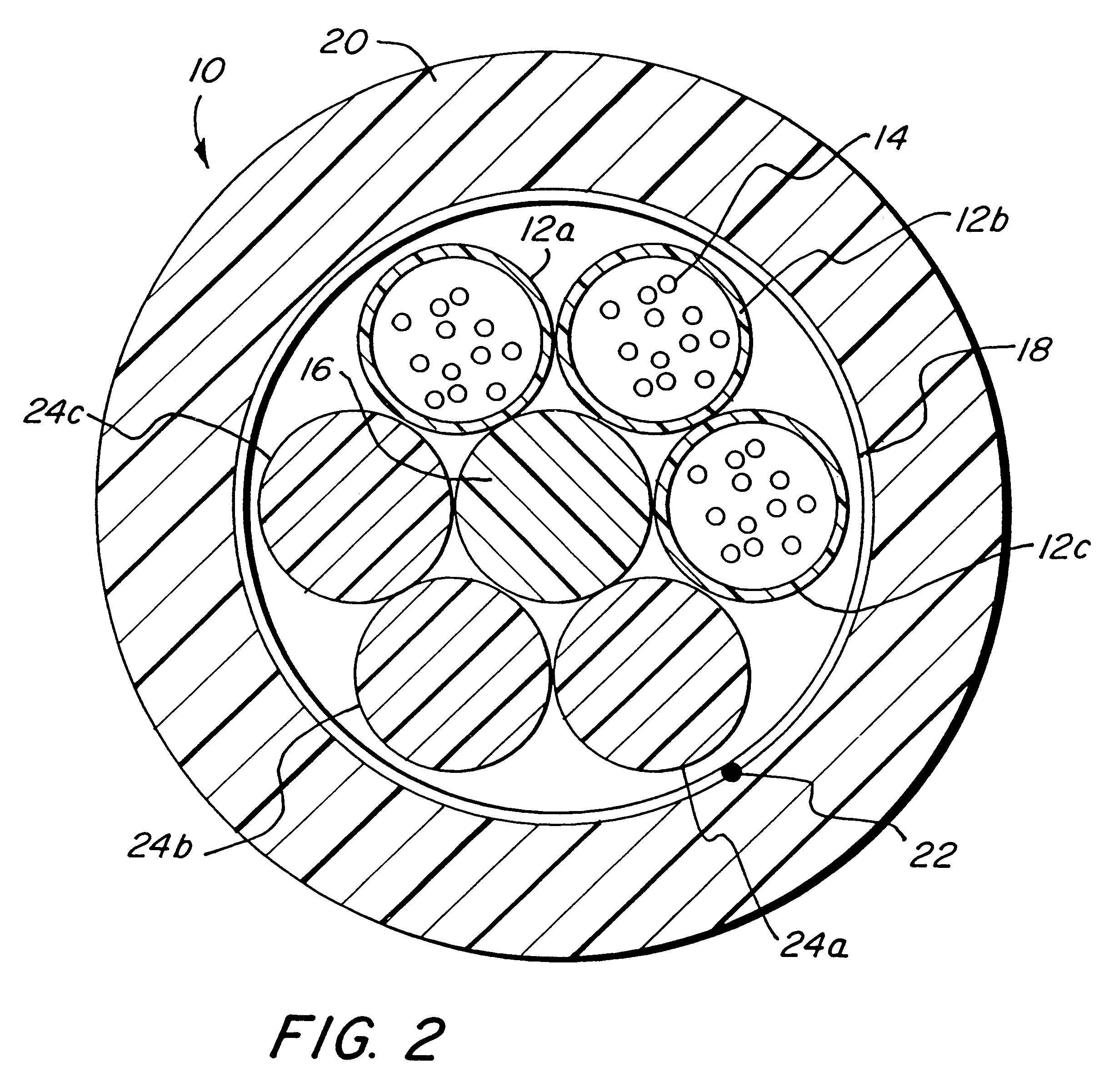
Referring to FIG. 2, when a cable having a fiber count lower than 72 fibers, for example, is desired, such as 36, some of the buffer tubes (12d-12f) are replaced by filler rods 24a-24c. These filler rods help to maintain the overall concentric structure and material properties of the lower count stranded optical fiber cable to be the same as the higher count fiber cable.

According to the present invention, it has been found that filler r...


PUM

PropertyMeasurementUnit
weight percentaaaaaaaaaa
shrinkageaaaaaaaaaa

Abstract

A filler rod for occupying space in a stranded optical fiber communications cable having at least one buffer tube containing at least one optical fiber is disclosed. The filler rod comprises an elongated rod extruded from a polypropylene homopolymer, a polypropylene-polyethylene copolymer (i-PP) resin material, or preferably, from a polypropylene-polyethylene copolymer having a nucleating agent disbursed therein. The resin material is foamed during extrusion so as to have a plurality of void spaces therein and a relative density which is less than 1 relative to the unfoamed resin material. As compared to rods made from high density polyethylene, the i-PP filler rods show a greater foaming efficiency, more efficient use of material, an improved combination of mechanical properties and density, reduced post-extrusion shrinkage and a substantial reduction in the sticking of the filler rods to the outer jacket that is experienced with high density polyethylene filler rods.

Description

1. Field of the InventionThe present invention relates to communications cables. More particularly, the present invention relates to filler rods for stranded optical fiber cables made from polypropylene based materials.2. Description of the Prior ArtOptical fiber cables have been in use in the communications industry for a number of years to transmit information at very high rates over long distances. Optical fiber cables come in a variety of configurations. The configurations include: cables with a centrally located single buffer tube containing one or more optical fibers; cables with a plurality of buffer tubes stranded in a helical or alternating helical arrangement about a central strength member; and cables with slotted cores in which a plurality of optical fibers reside.In stranded optical fiber cables, each of the buffer tubes typically contains up to 12 optical fibers or more, or in some cases ribbons. The buffer tubes are usually stranded in an alternating helical or S-Z co...

Claims


Application Information

Patent Timeline
Patent Type & Authority Patents(United States)
IPC IPC(8): G02B6/44
CPCG02B6/4401Y10T428/2973Y10T428/2927Y10T428/2969Y10T428/294Y10T428/2933Y10T428/2938Y10T428/2975Y10T428/2967Y10T428/2964G02B6/441G02B6/443
Inventor RISCH, BRIAN G.HOLDER, JAMES D.
Owner DRAKA COMTEQ BV
Why Eureka
Try Eureka