Dual-window high-power conical horn antenna

a conical horn and dual-window technology, applied in the field of antennas, can solve the problems of air breaking down and ionizing, limiting the performance of the antenna, and the conventional rf antenna is not typically capable of operating effectively at such high power levels

Inactive Publication Date: 2001-04-03
RAYTHEON CO
View PDF3 Cites 317 Cited by
  • Summary
  • Abstract
  • Description
  • Claims
  • Application Information

AI Technical Summary

Problems solved by technology

Unfortunately, conventional RF antennas are not typically capable of operating effectively at such high power levels.
This is due to the fact that at high power levels, the electric field at the output of the antenna is general...

Method used


Image

  • Dual-window high-power conical horn antenna
  • Dual-window high-power conical horn antenna
  • Dual-window high-power conical horn antenna

Examples


Embodiment Construction

Illustrative embodiments and exemplary applications will now be described with reference to the accompanying drawings to disclose the advantageous teachings of the present invention.

While the present invention is described herein with reference to illustrative embodiments for particular applications, it should be understood that the invention is not limited thereto. Those having ordinary skill in the art and access to the teachings provided herein will recognize additional modifications, applications, and embodiments within the scope thereof and additional fields in which the present invention would be of significant utility.

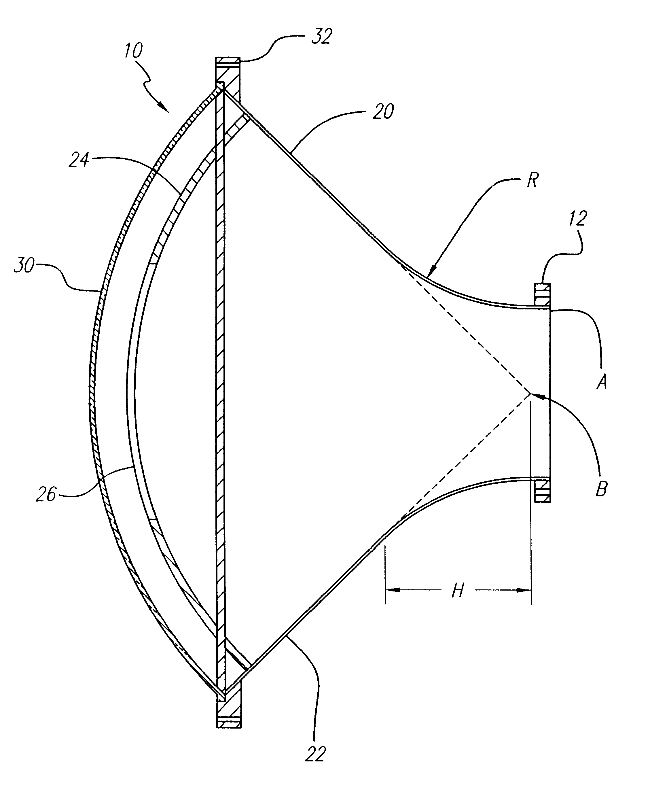
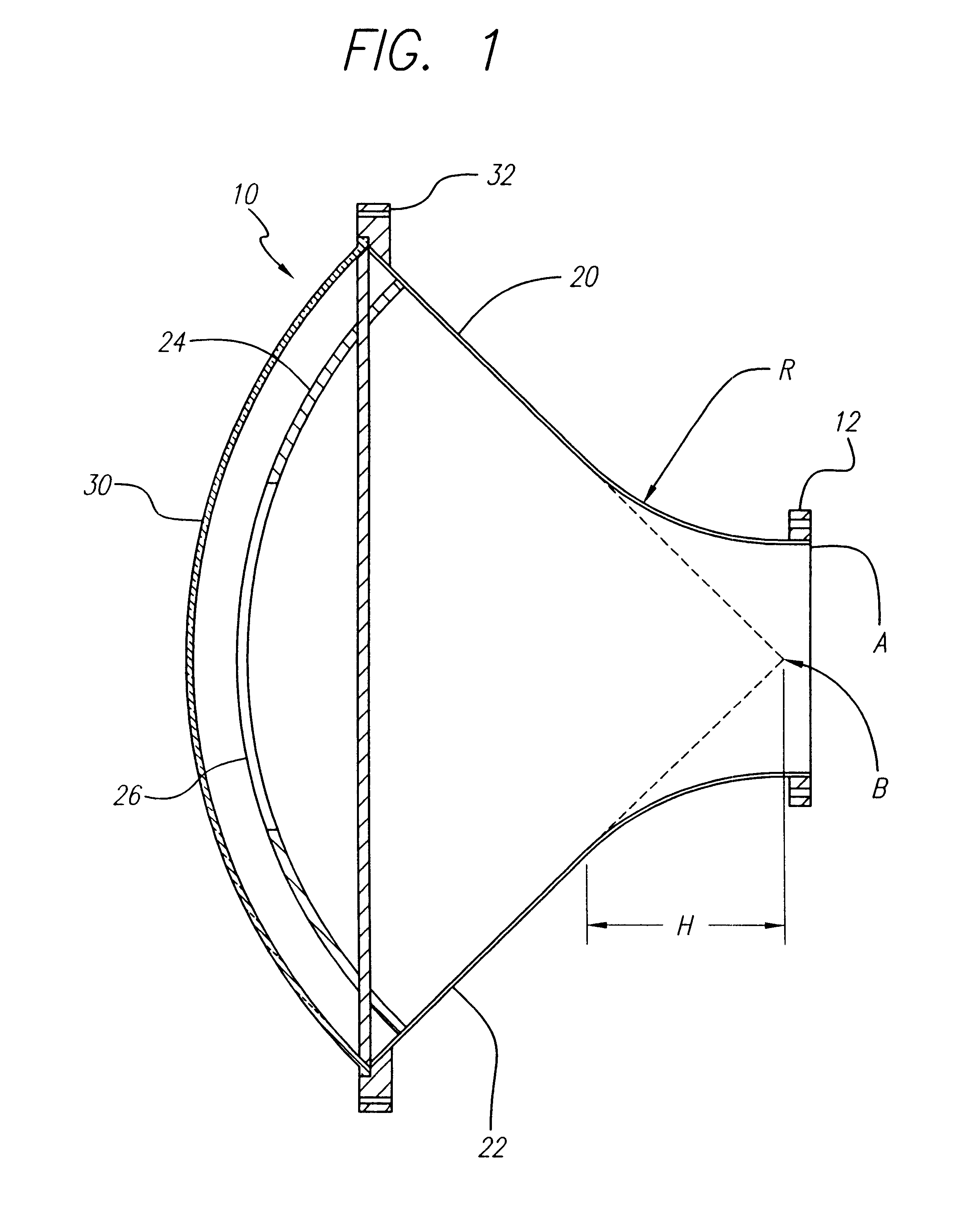
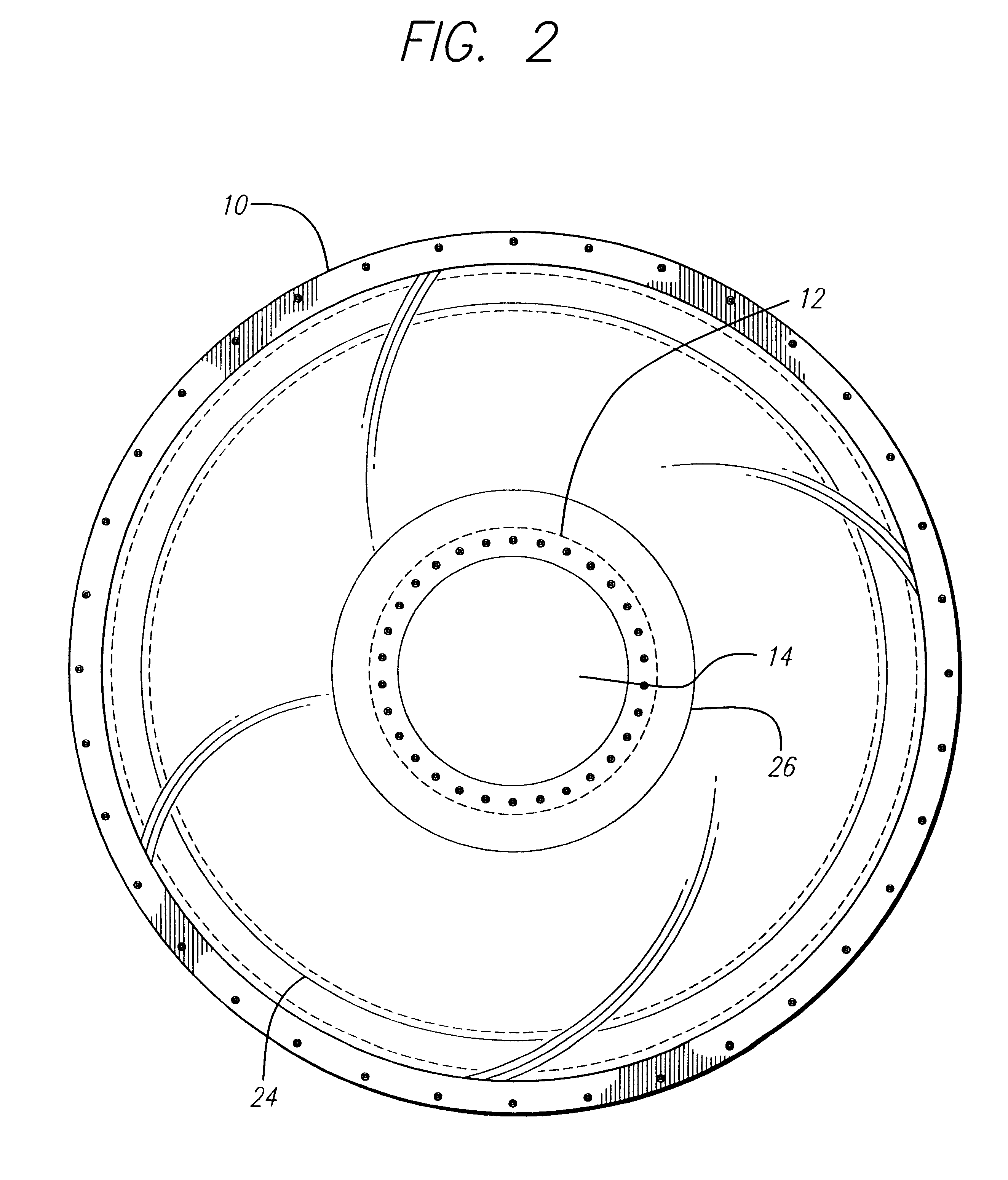
The present invention is a dual window TM.sub.01 mode conical horn antenna capable of radiating long pulses at high power. FIG. 1 is a sectional side view of the dual window antenna of the present invention. FIG. 2 is an end view into the aperture of the dual window antenna of the present invention. As shown in FIGS. 1 and 2, the inventive antenna 10 has an inpu...


PUM


Abstract

A high power TM01 mode radio frequency antenna. The inventive antenna comprises a conical horn for receiving an electromagnetic input signal and radiating an output signal in response thereto. An inner window is disposed within the conical horn. An outer window is mounted at an output aperture of the conical horn in alignment with the inner window. The antenna has a gradual taper from a waveguide input to the aperture over a cone angle of 45 degrees. The outer window is mounted at the aperture in concentric alignment with the inner window. For an optimal compact design, the inner and outer windows are of polycarbonate construction.

Description

1. Field of the InventionThe present invention relates to antennas. More specifically, the present invention relates to high power radio frequency antennas.2. Description of the Related ArtFor certain applications, there is a need for a high power radio frequency (RF) antenna capable of radiating large amounts (e.g. 3 gigawatts) of RF power with long pulse durations on the order of one microsecond. Unfortunately, conventional RF antennas are not typically capable of operating effectively at such high power levels. This is due to the fact that at high power levels, the electric field at the output of the antenna is generally so high as to cause the air to break down and ionize. The ionized air conducts and limits the performance of the antenna. Further, the high power sources that could be used with such antennas are typically sensitive to reflections.In addition, to the extent that conventional antennas have been used for high power applications, the antennas have been driven with s...

Claims


Application Information

Patent Timeline
IPC IPC(8): H01Q13/02H01Q13/00H01Q1/42
CPCH01Q1/42H01Q1/422H01Q13/02
Inventor CROUCH, DAVID D.DOLASH, WILLIAM E.
Owner RAYTHEON CO
Why Eureka
Try Eureka