Dual- and quad-ridged horn antenna with improved antenna pattern characteristics

Active Publication Date: 2005-10-20
TDK CORPARATION
View PDF8 Cites 39 Cited by
  • Summary
  • Abstract
  • Description
  • Claims
  • Application Information

AI Technical Summary

Benefits of technology

[0022] In some embodiments, the broadband horn antenna may include a cavity structure integrated within, or otherwise coupled to, a base of the pair of conductive antenna elements. Such a cavity structure may include at least one input connector for supplying current to the pair of conductive antenna elements. In some cases, a balanced input may be coupled to the at least one input connector for su

Problems solved by technology

These side lobes generally detract from the overall performance of the antenna by reducing the amount of EM energy radiated in the intended direction.
Thus, the antenna gain will be less than the directivity for antenna designs, which provide less than 100 percent radiation efficiency (i.e., real antennas).
However, the upper frequency range is often beset with anomalies in the radiation pattern.
However, due to tolerance constraints, the strip-like conductor fails to provide a viable solution to the radiation pattern anomalies at all times. For example, the strip-like conductor must be symmetrically arranged between the ridges with an exceptionally tight tolerance.
Not only is this difficult to accomplish in dual-ridged antenna designs, but it becomes exceedingly so in quad-ridged antenna designs, due the even tighter space constraints

Method used


Image

  • Dual- and quad-ridged horn antenna with improved antenna pattern characteristics
  • Dual- and quad-ridged horn antenna with improved antenna pattern characteristics
  • Dual- and quad-ridged horn antenna with improved antenna pattern characteristics

Examples


Embodiment Construction

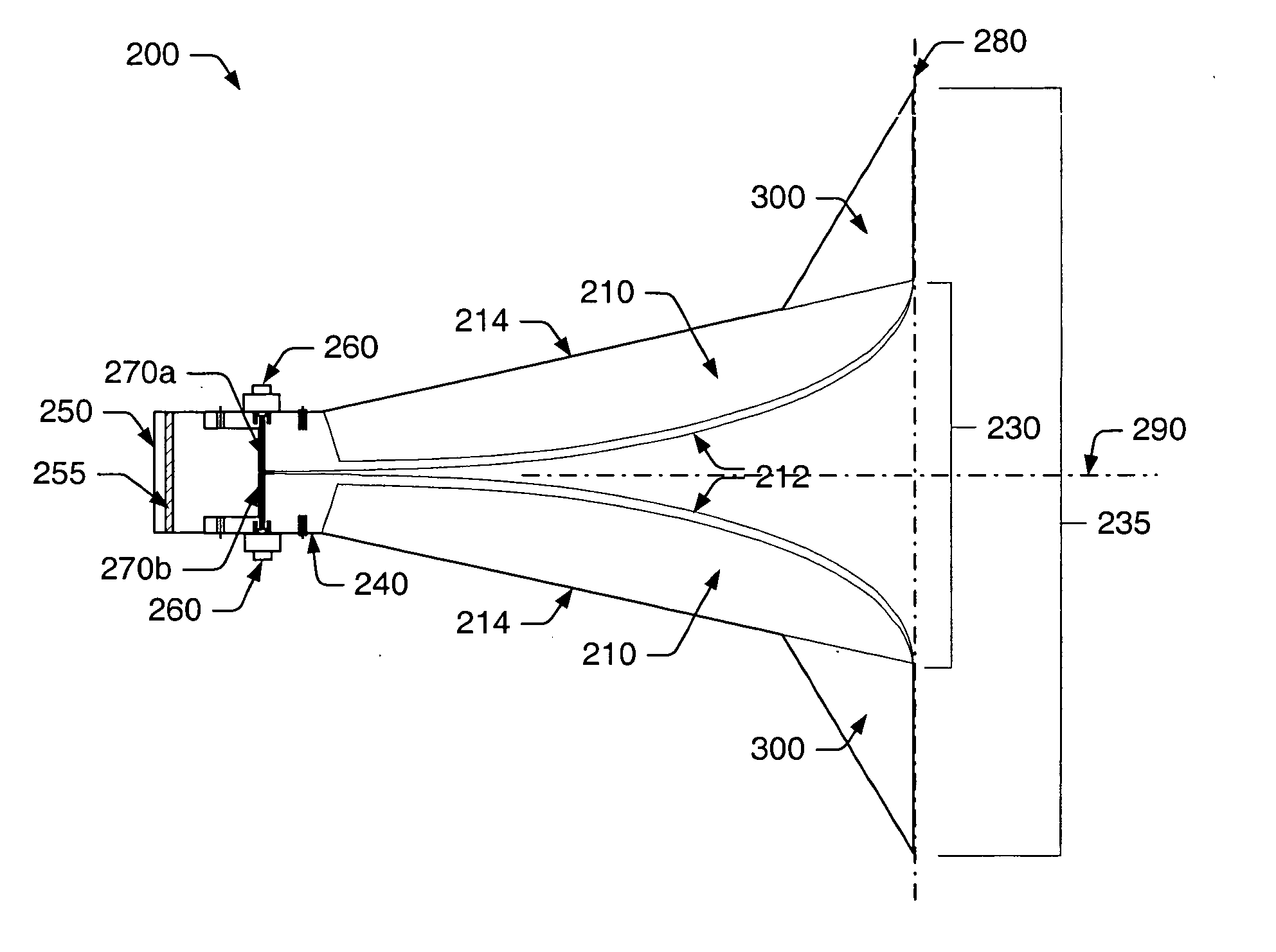
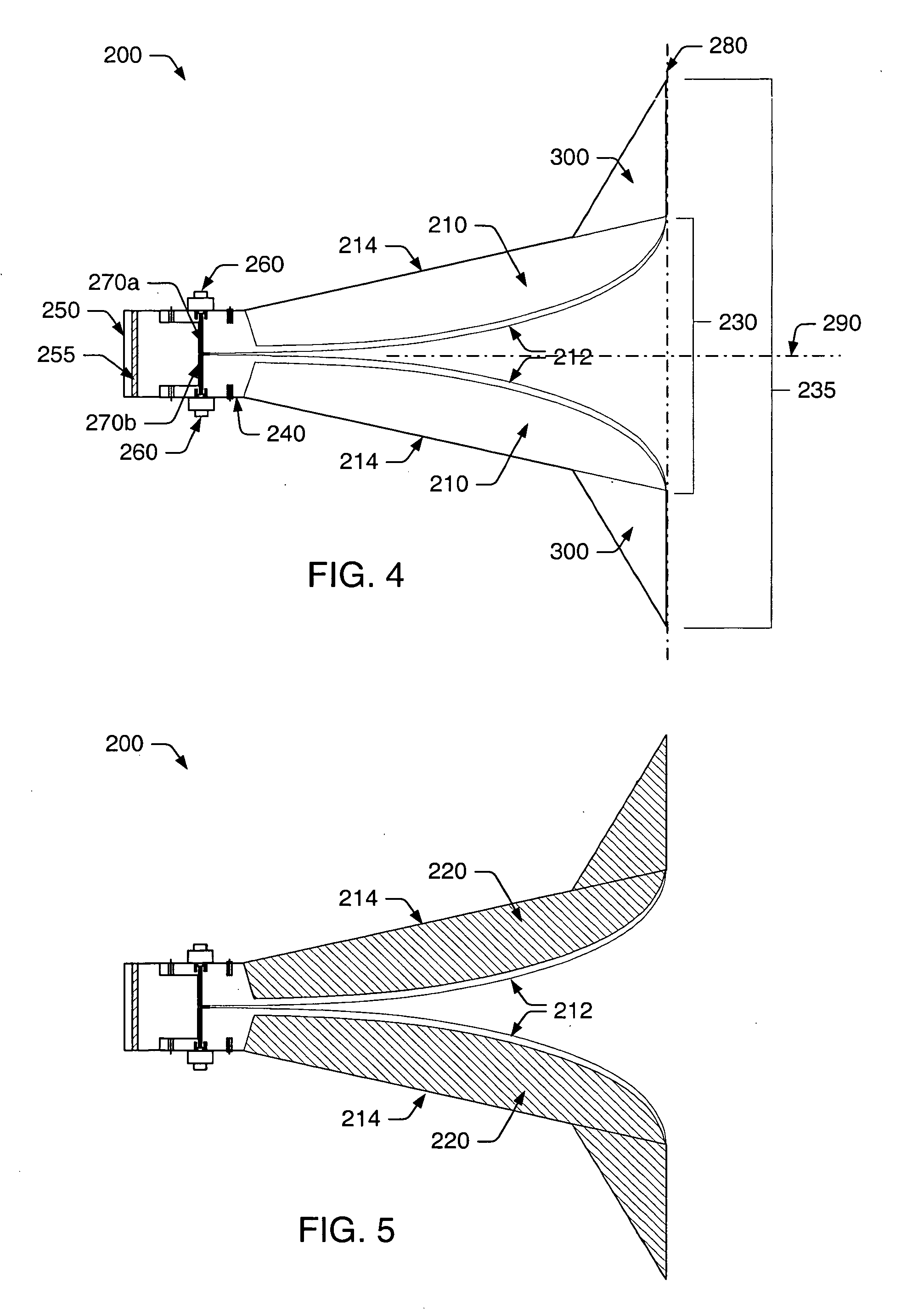
[0036] Turning to the drawings, exemplary embodiments of a dual-ridge and quad-ridge horn antenna are shown in FIGS. 4-11. As will be described in more detail below, the antenna design provided herein improves upon conventional designs by: (i) modifying the contour of the antenna elements to include tapered extension elements at the mouth of the antenna, (ii) the use of a relatively high impedance magnetic material on the antenna elements for the purpose of controlling, directing, channeling or otherwise guiding the surface currents in a direction conducive to radiation from the horn antenna, (iii) the use of longitudinal grooves formed within the antenna elements to suppress high-order modes in the feed region, (iv) the use of a high impedance and / or lossy magnetic material to suppress higher-order modes in the feed region, and (v) the use of a complementary, balanced feed for supplying equal and opposite amounts of current to the antenna elements, thus, reducing cross-polarization...


PUM


Abstract

As provided herein, a dual- or quad-ridged broadband horn antenna may include a pair of conductive antenna elements arranged opposite one another for guiding an electromagnetic wave in a longitudinal direction through the horn antenna. In some cases, the pair of conductive antenna elements may include substantially convex inner surfaces and appropriately shaped outer surfaces. The convex inner surfaces may generally function to direct or guide the radiated energy without disturbing the intended radiation pattern. To maintain the intended radiation pattern, the broadband horn antenna may also include a pair of tapered extension elements, each coupled to an outer surface of a different one of the antenna elements at one end thereof. In some cases, a magnetic material may be arranged upon at least a portion of the antenna elements to restrict surface currents to flowing along the inner surfaces only. In some cases, longitudinal grooves may be formed within the inner surfaces to restrict surface currents from flowing in a direction transverse to the longitudinal direction.

Description

PRIORITY APPLICATION [0001] This application claims priority to Provisional Application No. 60 / 563,965 filed Apr. 20, 2004 entitled “Dual- and Quad-Ridged Horn Antenna with Improved Antenna Pattern Characteristics.”BACKGROUND OF THE INVENTION [0002] 1. Field of the Invention [0003] This invention relates to antenna design and, more particularly, to dual-ridged and quad-ridged broadband horn antennas. [0004] 2. Description of the Related Art [0005] The following descriptions and examples are not admitted to be prior art by virtue of their inclusion within this section. [0006] An antenna is a device which can radiate or receive electromagnetic (EM) energy. An ideal transmitting antenna receives power from a source (e.g., a power amplifier) and radiates the received power into space. That is, electromagnetic energy escapes from the antenna and, unless reflected or scattered, does not return. A practical antenna, however, generates both radiating and non-radiating EM field components. A...

Claims


Application Information

Patent Timeline
IPC IPC(8): H01Q13/00H01Q17/00H01Q13/02H01Q13/04
CPCH01Q13/0275B42F7/025B42F3/003B42F9/008G09F23/00B42F7/065B42F13/16B42P2221/06B42P2221/10B42P2241/02
Inventor MCLEAN, JAMES S.SUTTON, ROBERT A.
Owner TDK CORPARATION
Why Eureka
Try Eureka