
Back-fed millimeter wave broadband double ridged horn antenna

A ridge horn and millimeter-wave technology, applied in the field of microwave and millimeter-wave signal processing, can solve the problems of poor coaxial feeding performance, inconvenient connection, and inability to carry out accurate and effective design, and achieve the effect of good performance and compact structure

Inactive Publication Date: 2009-12-02
UNIV OF ELECTRONICS SCI & TECH OF CHINA
View PDF0 Cites 42 Cited by
  • Summary
  • Abstract
  • Description
  • Claims
  • Application Information

AI Technical Summary

Problems solved by technology

In order to be able to match better, the probe head should have a gradual change, but when the shape of the probe is irregular, the surface current distribution cannot be obtained accurately, so the theoretical analysis and calculation are difficult, resulting in the inability to carry out accurate and effective design, making the manufactured The performance of the coaxial feed part is poor, and the input standing wave is relatively large, especially in the case of millimeter wave and wide frequency band
In addition, because the coaxial connector and the waveguide form an angle of 90 degrees, it is inconvenient to connect in some cascaded systems, and when the transmission power is large, the top of the probe is prone to breakdown

Method used


Image

  • Back-fed millimeter wave broadband double ridged horn antenna
  • Back-fed millimeter wave broadband double ridged horn antenna
  • Back-fed millimeter wave broadband double ridged horn antenna

Examples


Embodiment Construction

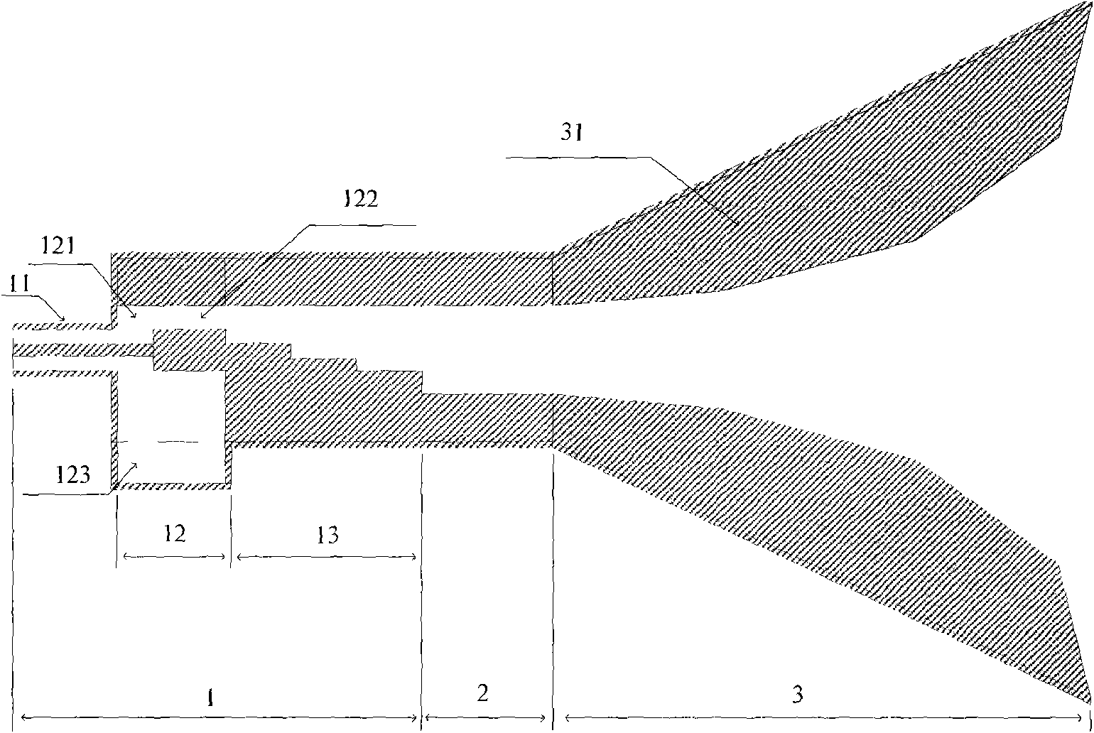
[0018] A feed-back millimeter-wave broadband double-ridge horn antenna, such as figure 1 As shown, it includes three parts: a coaxial line excitation part 1 , which includes a coaxial line 11 , a mode conversion part 12 and an impedance matching part 13 . The coaxial joint of the coaxial line 11 can be a 2.4 type or a 2.92 type coaxial joint, and its inner conductor is inserted into the inner conductor of the ridge side coaxial line 122 through the coupling hole, and glued firmly with conductive glue. The total length of the mode conversion part 12 is a quarter wavelength of the center frequency, and is divided into two parts: the former part is a shielded flat line 121 with a ridge, and the latter part is a ridged coaxial line 122, both of which are The TEM wave transmission line structure is designed with a characteristic impedance of 50Ω, and a rectangular groove, namely the ridge 123, is opened on the metal wall below the mode conversion part. The step impedance matching ...


PUM


Abstract

The invention provides a back-fed millimeter wave broadband double ridged horn antenna, belongs to the technical field of microwave and millimeter wave signal processing, and relates to a millimeter wave broadband horn antenna. The back-fed millimeter wave broadband double ridged horn antenna comprises a coaxial line excitation part, a ridge waveguide part and a double ridged horn part, wherein the coaxial line excitation part is formed by orderly connecting a coaxial line, a mode converting part and an impedance matching part; the mode converting part is formed by connecting a shielding panel line provided with a ridge and a coaxial line on the ridge side; the impedance matching part is stepped gradient double ridged waveguide; the ridge waveguide part is standard double ridged waveguide; and two ridges of the double ridged horn part are extended from two ridges of the ridge waveguide part to a mouth of a horn. The antenna adopts a back-fed structure, electromagnetic waves are fed in from the back of the ridge waveguide parallel to the ridge waveguide transmission direction, the coaxial line and the waveguide are positioned in the same axes, and a small voltage standing wave ratio can be obtained; and through mode conversion and impedance matching, the antenna can have satisfactory characteristics in a broadband range between 18 and 40GHz, and is characterized by wide frequency band, compact structure and good performance.

Description

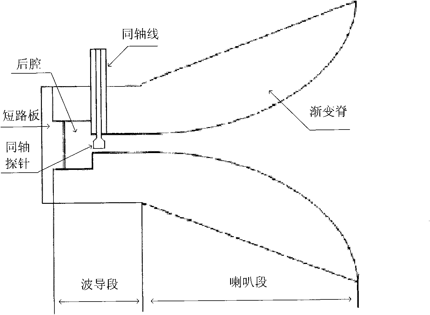
technical field [0001] The invention belongs to the technical field of microwave and millimeter wave signal processing, and relates to a millimeter wave antenna, in particular to a millimeter wave broadband horn antenna. Background technique [0002] With the development of millimeter-wave technology, its role in aerospace, meteorological communication and modern military systems is becoming more and more important. Horn antennas are widely used in this field due to their large power capacity, wide frequency band, high gain and good directivity. The application and development, usually used as an independent antenna and feed. In order to extend the working frequency band of the antenna, it is necessary to add ridges to the horn antenna. [0003] The millimeter-wave double-ridged horn antenna (such as figure 1 (shown) is an in-line double-ridge horn antenna. The coaxial feed probes are inserted perpendicular to the E-plane of the waveguide, and a short circuit board is adde...

Claims


Application Information

Patent Timeline
IPC IPC(8): H01Q13/04
Inventor 周杨郭高凤李恩苏胜皓
Owner UNIV OF ELECTRONICS SCI & TECH OF CHINA
Learn More