Microwave and millimeter wave ultra-wideband low-phase-shift six-digit digital attenuator

A digital attenuator and millimeter-wave technology, applied in impedance networks, electrical components, multi-terminal pair networks, etc., can solve the problems of large VSWR ratio of input and output terminals in attenuation state, defects in circuit topology and process implementation methods, and electrical performance indicators Difficult to meet the requirements and other problems, to achieve the effect of high attenuation accuracy, excellent comprehensive electrical performance indicators, and simple design

Inactive Publication Date: 2014-06-04
WUXI NANLIGONG TECH DEV
View PDF5 Cites 0 Cited by
  • Summary
  • Abstract
  • Description
  • Claims
  • Application Information

AI Technical Summary

Problems solved by technology

Similar products of microwave and millimeter wave ultra-broadband low-phase-shift six-digit digital attenuators are usually difficult to meet the requirements of electrical performance indicators due to the defects of the circuit topology and process implementation methods used in the design.
The main disadvantages are: 1) The circuit topology is complex; 2) The design is difficult; 3) The process is difficult; 4) The insertion loss of each attenuation state is large; 5) The phase shift of each attenuation state is large; The voltage standing wave ratio of the input and output terminals in the attenuation state is large; 8) the working frequency band is narrow; 9) the circuit size is large; 10) the control is complicated and inconvenient to use
In particular, the large phase shift of each attenuation state is a common shortcoming of many similar products, which limits the wide application of this type of product in phased array radar systems and many advanced communication systems and weapon systems

Method used


Image

  • Microwave and millimeter wave ultra-wideband low-phase-shift six-digit digital attenuator
  • Microwave and millimeter wave ultra-wideband low-phase-shift six-digit digital attenuator
  • Microwave and millimeter wave ultra-wideband low-phase-shift six-digit digital attenuator

Examples


Embodiment 1

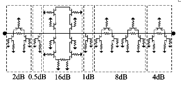
[0021] Example 1. combine figure 1 , figure 2 , the microwave and millimeter wave ultra-broadband low-phase-shift six-digit digital attenuator of the present invention, the 0.5dB attenuation unit adopts gallium nitride high electron mobility transistor as the ultra-broadband switch control device, and adopts a T-type topology.

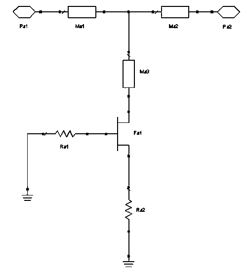
[0022] figure 2 The scheme consists of a 0.5dB attenuation unit consisting of the first microwave and millimeter wave input port Pa1, the first microwave and millimeter wave output port Pa2, the first gallium nitride high electron mobility transistor Fa1, the first microstrip line Ma1, and the second microstrip line Ma2 The third microstrip line Ma3 is composed of two first resistors Ra1 and second resistors Ra2. The microwave and millimeter wave input port Pa1 is connected to one end of the first microstrip line Ma1, and the other end of the first microstrip line Ma1 is connected to the second microstrip line. One end of the line Ma2, the other en...

Embodiment 2

[0023] Example 2. combine figure 1 , image 3 , the microwave and millimeter wave ultra-broadband low-phase-shift six-digit digital attenuator of the present invention, the 1dB attenuation unit adopts gallium nitride high electron mobility transistor as the ultra-broadband switch control device, and adopts a T-type topology.

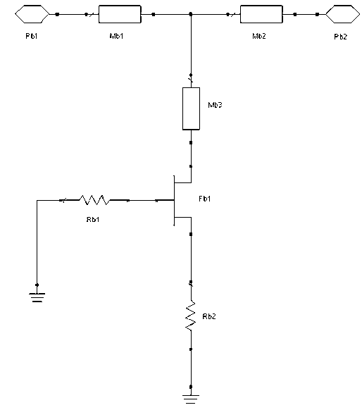
[0024] image 3 The scheme consists of a 1dB attenuation unit consisting of a second microwave and millimeter wave input port Pb1, a second microwave and millimeter wave output port Pb2, a second gallium nitride high electron mobility transistor Fb1, a fourth microstrip line Mb1, a fifth microstrip line Mb2, The sixth microstrip line Mb3 is composed of the third resistor Rb1 and the fourth resistor Rb2. The second microwave and millimeter wave input port Pb1 is connected to one end of the third microstrip line Mb1, and the other end of the third microstrip line Mb1 is connected to the fifth microstrip line. One end of the line Mb2, the other end of t...

Embodiment 3

[0025] Example 3. combine figure 1 , Figure 4 , the microwave and millimeter wave ultra-broadband low-phase-shift six-digit digital attenuator of the present invention, the 2dB attenuation unit adopts gallium nitride high electron mobility transistor as the ultra-broadband switch control device, and adopts a T-type topology.

[0026] Figure 4 The scheme consists of the third microwave and millimeter wave input port Pc1, the third microwave and millimeter wave output port Pc2, the third gallium nitride high electron mobility transistor Fc1, the seventh microstrip line Mc1, the eighth microstrip line Mc2, and the ninth microstrip line Mc3 is composed of the fifth resistor Rc1 and the sixth resistor Rc2, the third microwave and millimeter wave input port Pc1 is connected to one end of the seventh microstrip line Mc1, and the other end of the seventh microstrip line Mc1 is connected to one end of the eighth microstrip line Mc2, The other end of the eighth microstrip line Mc2...


PUM


Abstract

The invention discloses a microwave and millimeter wave ultra-wideband low-phase-shift six-digit digital attenuator. The attenuator comprises a 0.5dB attenuation unit, a 1dB attenuation unit, a 2dB attenuation unit, a 4dB attenuation unit, an 8dB attenuation unit and a 16dB attenuation unit which are cascaded, wherein the 0.5dB / 1dB / 2dB attenuation units adopt a T-type topological structure, and the 4dB, 8dB, 16dB attenuation units adopt an inverted U-shaped topological structure; the cascading sequence of the attenuation units is 2dB, 0.5dB, 16dB, 1dB, 8dB and 4dB; the working frequency of the attenuator is within the range of 32-38GHz; and 64 attenuation states can be realized in the attenuation range of 0.5-31.5dB by taking the 0.5 dB as a step value. The attenuator has the advantages of simple circuit topological structure, small attenuation state phase shift, low insertion loss, high attenuation accuracy, low standing-wave ratio of input terminal and output terminal voltages, wide working band, small circuit dimension and convenience for adopting a MMIC (Monolithic Microwave Integrated Circuit) technology for batch production.

Description

technical field [0001] The invention relates to an electronic component used for radar, communication and guidance, in particular to a microwave and millimeter wave ultra-wideband low-phase-shift six-digit digital attenuator. Background technique [0002] Microwave and millimeter wave ultra-wideband low phase shift six-digit digital attenuator is an electronic component mainly used in electronic system equipment such as digital microwave communication, mobile communication, radar, electronic countermeasures, guidance and instruments. In the ultra-broadband microwave and millimeter wave frequency band control circuit, the microwave and millimeter wave digital attenuator is one of the main control circuits. The main technical indicators describing the performance of this product are: 1) Operating frequency bandwidth; 2) Attenuation bits; 3) Total attenuation; 4) Attenuation step; 5) Attenuation accuracy; 6) Insertion loss of each attenuation state; 7) Phase shift of each atten...

Claims


Application Information

Patent Timeline
Patent Type & Authority Patents(China)
IPC IPC(8): H03H7/03
Inventor 戴永胜孙宏途戚湧汉敏尹洪浩李平陈日清谢秋月韩群飞冯媛左同生
Owner WUXI NANLIGONG TECH DEV
Why Eureka
Try Eureka