Low-intermodulation antenna stern line connector

A tail cable connector and antenna technology, which is applied in the direction of antenna connector, antenna grounding switch structure connection, connection, etc., can solve problems such as unreliable crimping, poor index stability, and difficult processing, so as to improve effective power transmission and reduce Machining error, effect of simple machining process

Inactive Publication Date: 2015-04-01
安徽蓝麦通信股份有限公司
View PDF5 Cites 1 Cited by
  • Summary
  • Abstract
  • Description
  • Claims
  • Application Information

AI Technical Summary

Problems solved by technology

There are four major disadvantages in this method: first, the cost of the product is high, there are too many parts, repeated clamping, processing, and electroplating are required, the consumption of raw materials is large, the processing is difficult, the processing cycle is long, the cost is high, and there is no market competition. The second is difficult assembly: after the cable 10 is welded to the welding head 5, the shell 8 and the press sleeve 9 must be punched sequentially. During the process, the cable 10 needs to be carefully protected, and the cable may be damaged if you are not careful; The third is that the index stability is poor. Since the entire product has too many parts and is a split structure, machining errors generated during the machining process are unavoidable. They are connected by crimping, and there are excessive dimensional errors and unreliable crimping, etc. , causing a great hidden danger to the stability of the electrical performance of the product
Fourth, it is cumbersome to use, because the cable joint of this structure is connected with the antenna panel through the installation thread 81, and the other end is also connected with another corresponding connector through the thread, and another connector When tightening, it is easy to unscrew the housing 8 from the antenna panel, resulting in damage to the antenna

Method used


Image

  • Low-intermodulation antenna stern line connector
  • Low-intermodulation antenna stern line connector
  • Low-intermodulation antenna stern line connector

Examples


Embodiment

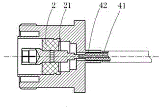
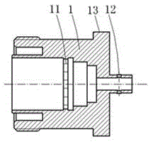
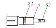
[0016] Example: Combine Figures 1A-1C , the DIN-type low-intermodulation antenna tail cable connector for matching 670-141SXE radio frequency cables in this embodiment includes: an integral outer conductor 1, an insulator 2 filled with a medium and a central conductor 3; the insulator 2 is a high temperature resistant material The sintered double-ring structure is located between the outer conductor 1 and the central conductor 3 to realize the fixing of the outer conductor and the central conductor; the tail of the central conductor 3 is provided with a central welding hole, which can realize welding with the inner conductor 41 of the radio frequency cable. The setting of the exhaust hole 31 plays a role in ensuring the welding strength, and realizes the connection between the inner conductor 41 of the radio frequency cable and the center conductor 3; Welding, the setting of the drainage hole 12 can enhance the welding strength and realize the connection between the radio fre...


PUM


Abstract

The invention discloses a low-intermodulation antenna stern line connector. The low-intermodulation antenna stern line connector comprises an integrated outer conductor, an insulator filled with a medium, and a central conductor; a signal transmission cavity with a coaxial structure is formed inside the outer conductor, and the tail part of the outer conductor is provided with a radio-frequency cable welding hole and a mounting flange; the insulator is formed by sintering a high-temperature resistant material and is of a dual-circle structure; the tail part of the central conductor is provided with a central welding hole required for welding a radio-frequency cable, and the central welding hole is gradual in a coaxial step manner. The low-intermodulation antenna stern line connector is simple in structure, reliable in mechanical performance, excellent in electric performance, high in assembly efficiency and high in raw material utilization rate, has low intermodulation performance and is suitable for large-batch production.

Description

technical field [0001] The invention relates to a low intermodulation antenna tail cable connector, in particular to a DIN type low intermodulation antenna tail cable connector matched with a 670-141SXE radio frequency cable. Background technique [0002] At present, for the common structure that the intermodulation of the DIN type connector mated with the 670-141SXE radio frequency cable is unstable and the electrical performance is poor. Such as figure 2 For a common structure, the specific operation is to first snap the welding head 5 into the inner hole of the insulator 6, insert the socket 7 into the inner hole of the welding head 5, and use a press to crimp the welding head 5 and the socket 7 into a As a whole, the cable 10 is passed through the hole at the tail of the shell 8, the inner core of the cable is welded together with the welding head 5, the insulator 6 is reversely loaded into the shell 8, and the pressing sleeve 9 is stamped into the Inside the housing...

Claims


Application Information

Patent Timeline
Patent Type & Authority Applications(China)
IPC IPC(8): H01R24/56H01R9/05H01Q1/50
CPCH01R13/02H01R13/516H01R13/73H01R24/44H01R2201/02
Inventor 齐磊
Owner 安徽蓝麦通信股份有限公司
Why Eureka
Try Eureka