
Low-loss stationary-phase 700PPM semi-rigid cable assembly
A cable assembly and low-loss technology, which is applied in the direction of electrical components, circuits, and two-component connection devices, can solve the problem that semi-rigid cable assemblies cannot meet low-loss phase stability at the same time, and achieve stable and reliable quality, excellent performance, and low cost. Effect of VSWR
- Summary
- Abstract
- Description
- Claims
- Application Information
AI Technical Summary
Problems solved by technology
Method used
Image

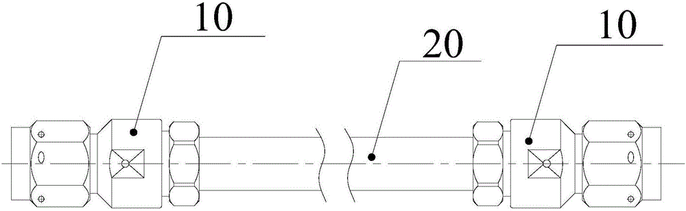
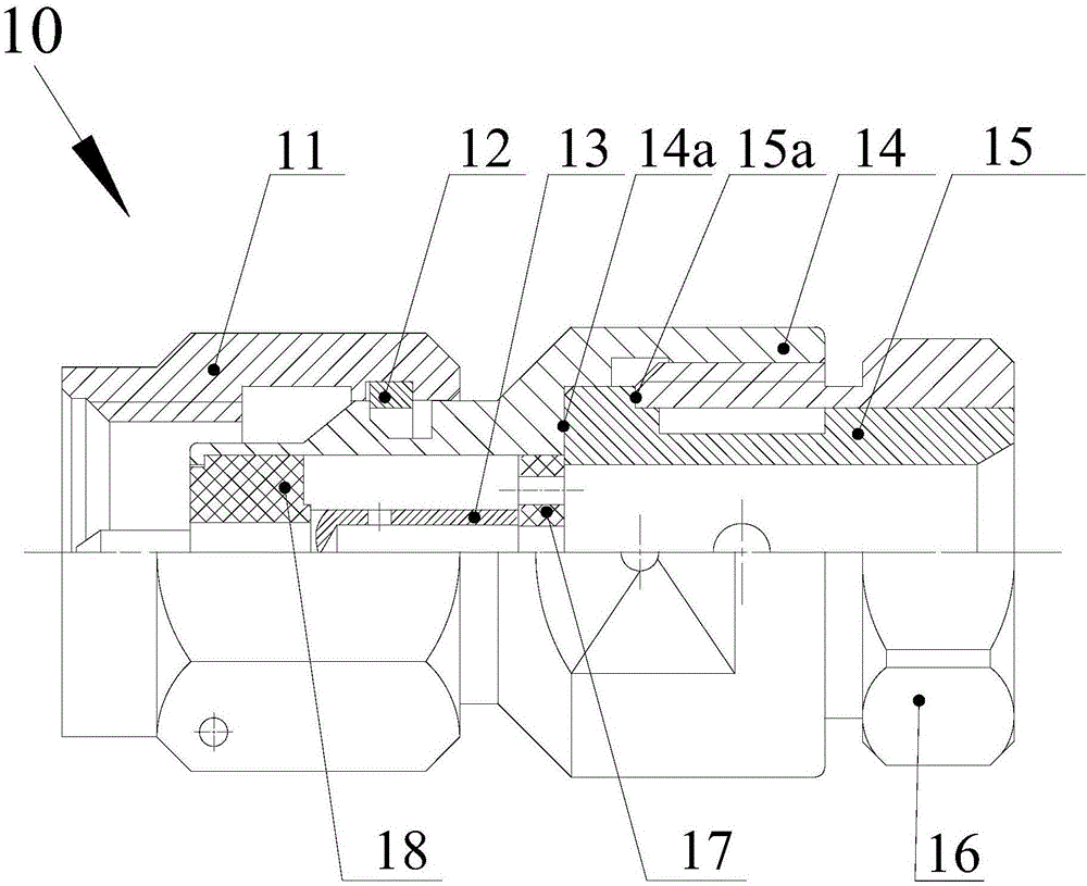
Examples
Embodiment Construction
[0008] Embodiments of the present invention are described in detail below in conjunction with the accompanying drawings:
[0009] Low loss phase stable 700PPM semi-rigid cable assembly, such as figure 1 with figure 2 As shown, it includes a semi-rigid cable 20 and a radio frequency connector 10. The RF connector 10 is composed of an inner conductor 13, an outer conductor 15, a front screw sleeve 11, a shell 14 and a tail sleeve 16. The shell 14 is inserted into the rear end of the front screw sleeve 11 and fixed with a snap ring 12. The first insulator 18 is inserted into the Installed in the shell 14, the front side of the shell 14 is closed to prevent the first insulator 18 from falling out; the inner conductor 13 is supported in the shell 14 through the first insulator 18, and the head end of the inner conductor 13 extends into the central thread of the front screw sleeve 11 In the hole, the inner conductor 13 is used for welding with the core wire of the semi-rigid cabl...
PUM
 Abstract
Description
Claims
Application Information