High-gain layered lens antenna based on optical transformation theory

A technology of lens antenna and optical transformation, applied in the direction of antenna, electrical components, etc., can solve the problems of designing high-gain lens antenna, etc., and achieve the effect of high degree of freedom, increased gain, and simple shape

Active Publication Date: 2009-03-04
SOUTHEAST UNIV
View PDF0 Cites 40 Cited by
  • Summary
  • Abstract
  • Description
  • Claims
  • Application Information

AI Technical Summary

Problems solved by technology

However, no one has so far applied the principles of optical transformations to design high-gain lens antennas

Method used


Image

  • High-gain layered lens antenna based on optical transformation theory
  • High-gain layered lens antenna based on optical transformation theory
  • High-gain layered lens antenna based on optical transformation theory

Examples


Embodiment Construction

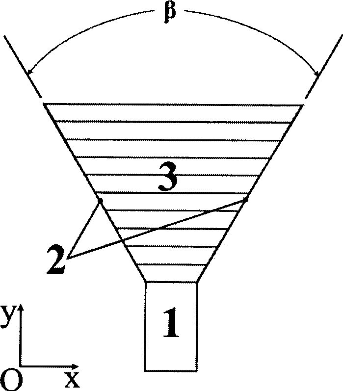
[0012] A high-gain layered lens antenna based on optical transformation theory, including a rectangular feeder waveguide 1, a metal conductor horn 2 is connected to the rectangular feeder waveguide 1, a layered lens 3 is embedded in the metal conductor horn 2, and the layered lens 3 The horn is filled and each layer of lenses is parallel to the aperture surface of the horn. The layered lens 3 is composed of non-uniform and anisotropic artificial electromagnetic materials. The direction of the electric field is perpendicular to the paper surface. The kth layer satisfies: μ x k = ϵ z k = 1 , μ y k = 1 / α k 2 , alpha k =1+(k-δ k )(b-a) / (na), where Indicates the permeability of the k-th layer...


PUM


Abstract

The invention relates to a high-gain layered lens antenna based on optical transform theory, comprising a rectangular feeding waveguide; a metallic conductor horn is connected with the rectangular feeding waveguide and internally embedded with a layered lens; the layered lens is filled with horns and each layer of the lens is parallel to the aperture surface of the horn; the layered lens is composed of non-uniform and anisotropic artificial electromagnetic material, the direction of the electric field is vertical to the paper surface and the k layer meets the following conditions: Mux is equal to Epsilonz which is equal to 1, Muy is equal to 1/Alphak<2> and Alphak is equal to 1 plus (k minus Deltak)(b-a)(na), wherein, Mux represents the magnetic permeability of the k layer of the lens in the x direction, Muy> is the magnetic permeability of the k layer of the lens in the y direction, Epsilonz is dielectric constant of the k layer of the lens in the z direction which is vertical to the paper surface, Alphak is an intermediate variable related to the k layer of the lens, n is the total number of the layers of the lens and the value range thereof is a certain integer between 10 to 50, k is the layer of the lens and the value thereof is between 1 and the total layers n, Deltak is a certain set constant between 0 to 1, a is the width of the feeding waveguide, and b is the aperture width of the horn antenna. The inclined angle Beta of the horn is between 60 DEG C and 150 DEG C. The invention has simple shape and high gain.

Description

technical field [0001] The present invention relates to a high-gain layered lens antenna, in particular to a multi-layer lens antenna with good orientation and high gain designed by applying the principle of optical transformation, which can be used in satellite communication to achieve high Directed communication. Background technique [0002] The principle of optical conversion is a tool for designing anisotropic new artificial electromagnetic materials jointly proposed by Professor Pendry of Royal Institute of Technology, Dr. Schrig and Professor Smith of Duke University in 2006 ("Controlling Electromagnetic Fields," Science 312, 1780, 2006) . At present, many scientific researchers use optical transformation methods to design transformation optical devices such as stealth coats and electromagnetic wave concentrators. In 2007, F.Kong et al. of Shandong University applied the principle of optical transformation to antenna design for the first time. They applied the princ...

Claims


Application Information

Patent Timeline
Patent Type & Authority Applications(China)
IPC IPC(8): H01Q19/08H01Q15/08
Inventor 崔铁军蒋卫祥马慧锋杨歆汨程强
Owner SOUTHEAST UNIV
Why Eureka
Try Eureka