Distributed infrastructure for wireless data communications

a technology for distributed infrastructure and wireless data, applied in the direction of wireless communication, data switching network, wireless communication, etc., can solve the problems of increasing the cost of the infrastructure, the load presented to the control point, and the architecture does not scale well

Inactive Publication Date: 2001-04-10
QUALCOMM INC
View PDF5 Cites 180 Cited by
  • Summary
  • Abstract
  • Description
  • Claims
  • Application Information

AI Technical Summary

Benefits of technology

Applicants provide a solution to the shortcomings of the previously described architecture by distributing the functionality of the control points and allowing the co-location of a co...

Problems solved by technology

This architecture suffers from several fundamental problems: the control points for each part of the network are single points of failure which must be made highly reliable, increasing their cost.
Furthermore, since they are unique for each network, the architecture does not scale well as the number of network access points increase, inc...

Method used


Image

  • Distributed infrastructure for wireless data communications
  • Distributed infrastructure for wireless data communications
  • Distributed infrastructure for wireless data communications

Examples


Embodiment Construction

FIG. 3

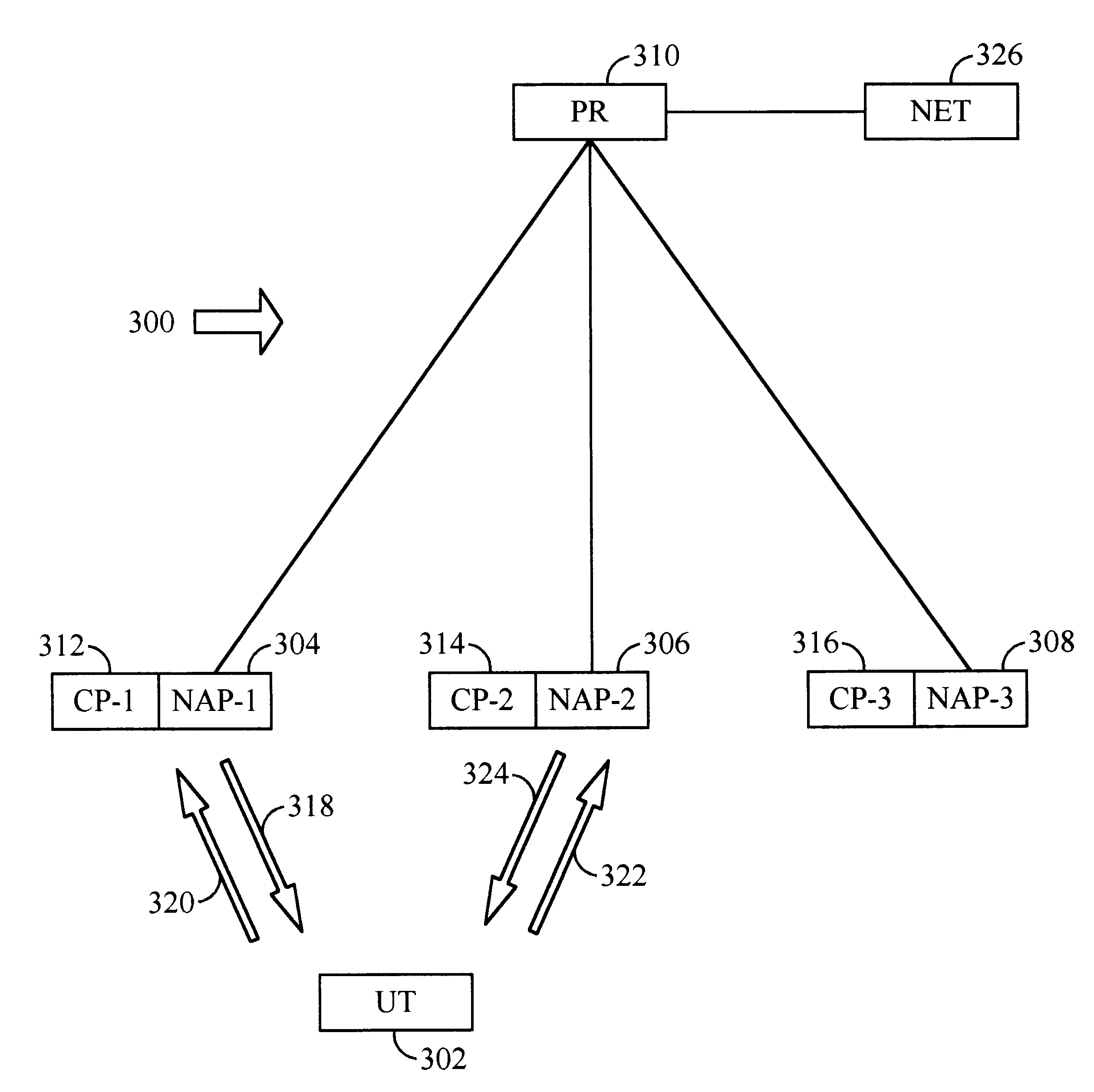
FIG. 3 shows a single-router wireless packet data network 300, according to the present invention.

A user terminal 302 is configured to transmit and receive wireless data packets. There is plurality of network access points 304-308, each being configured to transmit wireless data packets to, and to receive them from, the user terminal 302. A router 310 is capable of transmitting data packets to, and receiving them from, the network access points 304-308. FIG. 3 shows the situation in which a user terminal is leaving the area served by first network access point 304 and is entering the area served by second network access point 306.

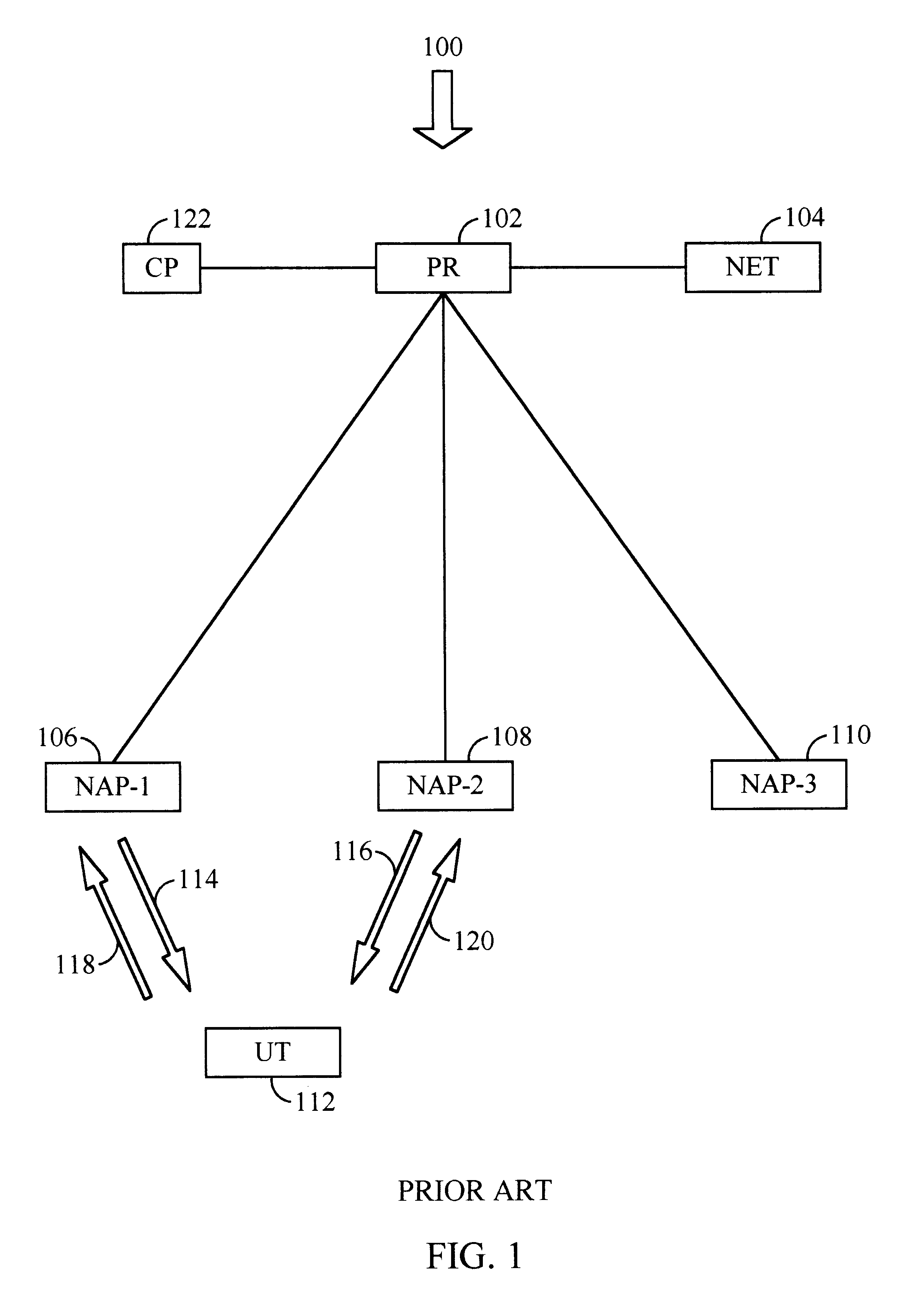
There is a plurality of control points 312-316. As in the prior art, each control point is configured to manage a wireless link 318-324 between the user terminal 302 and the selected network access point 304-308. However, there are plural control points 312-316 instead of a single control point 122. In this invention, a user terminal is served by the ...


PUM


Abstract

A mobile user terminal 402 accesses a packet data network 450 through one or more of several network access points 404-412. One or more control points 432-440 determines which network access point or points the user terminal is to access. Control may be retained in the current control point, or transferred to another control point, whenever it is convenient. There are preferably several routers, each having an associated home agent 418-420 which determines which foreign agents need to be accessed on behalf of each user terminal. There are several foreign agents 422-430, which forward packets received from a user terminal's home agent to the control point currently controlling communications with the user terminal.

Description

This invention pertains to wireless communications systems and, in particular, to wireless packet data networks.FIG. 1FIG. 1 shows a conventional single-router wireless packet data network 100. A packet router 102 receives data packets from the remainder of a network 104 and routes them to one or more network access points 106-110. The network access points 106-110 transmit the packets forward to a user terminal 112 over forward wireless links 114-116. The user terminal 112 transmits packets back to the network access points 106-110 over reverse wireless links 118-120. The user terminal 112 may be a cellular telephone carried by a person, a portable computer, a mobile telephone in an automobile, or any other mobile device which must continue to provide connectivity even while it moves.A control point 122 is connected to the packet router 102. It manages the wireless links 114-120. Management includes many functions. For example, as the user terminal 112 moves around the path loss be...

Claims


Application Information

Patent Timeline
IPC IPC(8): H04L29/06H04L12/28H04Q7/24H04L12/56H04B7/26H04L12/46H04W36/08H04W80/04H04W88/08H04W88/12
CPCH04W88/12H04W36/08H04W80/04H04W88/08
Inventor BENDER, PAUL E.GROB, MATTHEW S.KIMBALL, ROBERT H.KARMI, GADI
Owner QUALCOMM INC
Why Eureka
Try Eureka