
System and method for traffic localization

a traffic localization and packet routing technology, applied in the field of system and method for providing packet routing on a network, can solve the problems of no knowledge of either the routing policies of the network or the network layout of the mobile node, the network has little or no say on whether route optimization is necessary or whether

Active Publication Date: 2011-02-08
CISCO TECH INC
View PDF15 Cites 64 Cited by
  • Summary
  • Abstract
  • Description
  • Claims
  • Application Information

AI Technical Summary

Problems solved by technology

However, there are some significant drawbacks in doing route optimization only as defined in Mobile IPv6 RFC 3775.
However, the mobile node has no knowledge of either the routing policies of the network or the network layout.
So, the mobile nodes are likely to initiate return routability procedures without knowing whether there will be any difference in the way the IP packets are actually going to be routed.
Second, the network has little or no say on whether route optimization is necessary or whether it is even allowed for certain applications.
For example, if the operator has a policy that requires the route to be via a certain network segment or certain nodes (for packet inspection or security and charging policy enforcement), there is no standardized way to allow or disallow the mobile node to initiate route optimization on a per application basis.
Third, the route optimization solution with Mobile IPv6 only works for nodes with either dual stack or IPv6 routing infrastructure in the network.
It is costly for operators to completely switchover to an IPv6 network at one time.
Fourth, inter-access gateway (AGW) handoff management when mobile initiated route optimization is in use is very time consuming.
This not only adds over-the-air overhead, but also increases signal processing burden for the mobile and the network nodes.
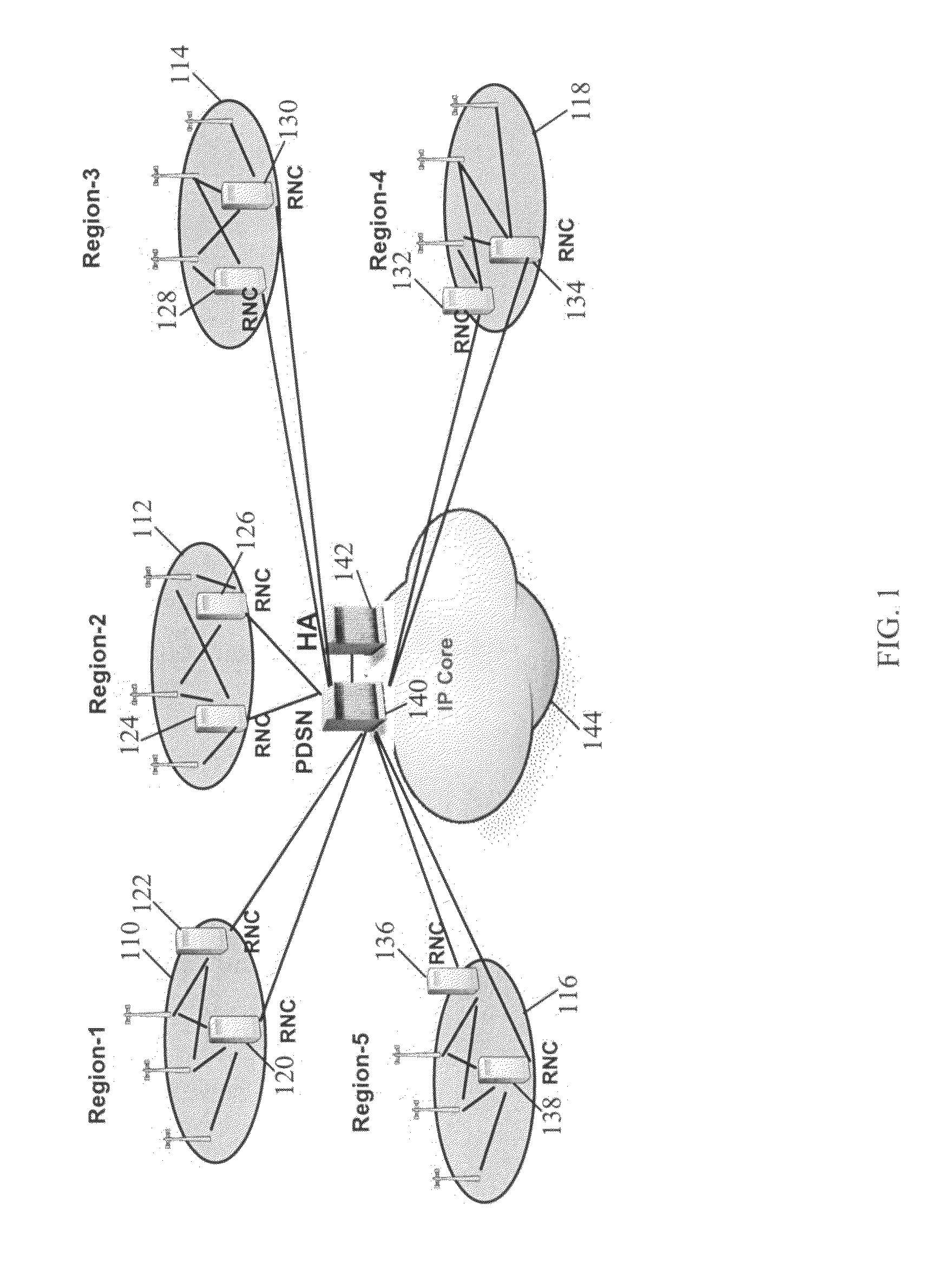
However, for conversational real time applications, the reverse tunneling causes additional data transport latency which may vary depending on the distance traveled and the number of devices involved (i.e., backhaul link type).

Method used


Image

  • System and method for traffic localization
  • System and method for traffic localization
  • System and method for traffic localization

Examples


Embodiment Construction

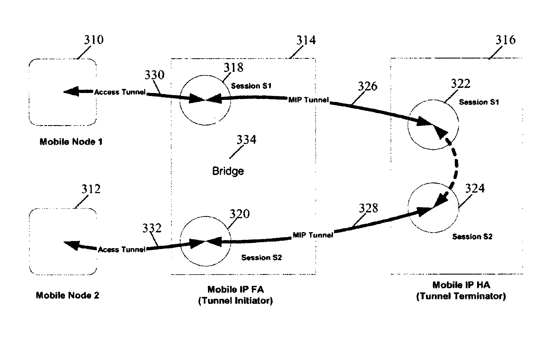
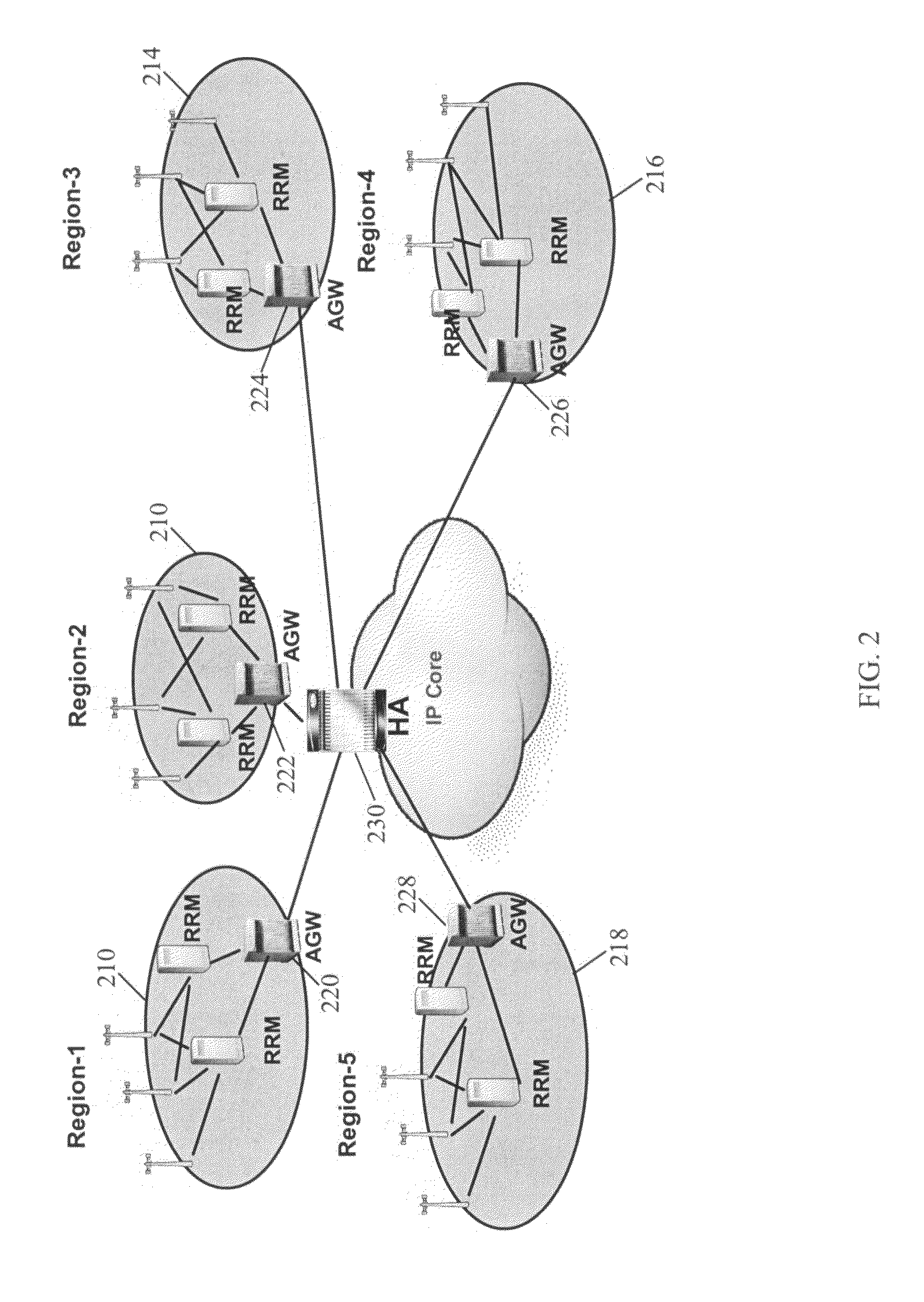
[0029]Systems and methods for bridging selected packet traffic are provided in some embodiments. The bridging can be accomplished by determining a node is a common tunnel initiator (e.g., shared by at least two devices on the same call session) and then bypassing the tunnel terminator(s) of the call session. Bridging at a tunnel initiator reduces the amount of traffic that is backhauled. The bridge can also reduce packet latency and jitter by eliminating the backhaul network hops. The bridge may be implemented at various points and on various devices in a network depending on the network topology. The bridge can be implemented on a foreign agent, an access gateway (AWG), a packet data serving node (PDSN), a foreign agent (FA), a mobility anchor point (MAP), a controlling access point (CAP), a local mobility anchor (LMA), a media gateway (MGW), a media gateway control function (MGCF), a call session control function (CSCF), or a home agent (HA).

[0030]Tunnels are deployed in routers a...


PUM


Abstract

Systems and methods for bridging packet flows to bypass call legs and / or tunnels are provided. A tunnel initiator, which can be an access gateway, a foreign agent, and a mobility anchor point, for example, provides a bypass for certain packets that have a destination serviced by the same tunnel initiator. The bridge allows the packets to bypass a backhaul loop and reduces latency and frees bandwidth for other purposes in the network. The bridging can be implemented in a tunnel initiator for mobile to mobile packet flows, mobile to land line packet flows, and land line to mobile packet flows. Route optimization can also be provided in certain embodiments.

Description

CROSS-REFERENCE TO RELATED APPLICATIONS[0001]This application claims benefit under 35 U.S.C. §119(e) of U.S. Provisional Patent Application No. 60 / 792,521, entitled “A System and Method for Tunnel Switching,” filed Apr. 17, 2006, and U.S. Provisional Patent Application No. 60 / 801,001, entitled “Traffic Localization via Network Based Route Optimization,” filed May 17, 2006, which are hereby incorporated by reference herein in their entireties.FIELD OF THE DISCLOSURE[0002]This invention relates to a system and method for providing packet routing on a network. More particularly, packet flows are bridged in a network to bypass backhaul call legs or tunnels when possible.BACKGROUND[0003]There have been a few attempts at Route Optimization (RO) solutions developed in the wireless industry. Recently, the notion of route optimization has become synonymous with Mobile IPv6. Mobile IPv6 as defined in RFC 3775, which is hereby incorporated by reference, includes details about using Return Rout...

Claims


Application Information

Patent Timeline
Patent Type & Authority Patents(United States)
IPC IPC(8): H04L12/56H04W8/08H04W80/04
CPCH04W8/082H04W28/06H04L67/14H04L67/148H04W40/34H04W48/16H04W76/022H04W80/04H04W76/12
Inventor HARPER, MATTHEW H.PUTHIYANDYIL, SANIL KUMARRAMANKUTTY, RAJESHRADHAKRISHNAN, SHAJI E.CHOWDHURY, KUNTAL
Owner CISCO TECH INC
Learn More