Access network system capable of reducing call loss probability

a network system and call loss technology, applied in the field of access network system, can solve problems such as increasing call loss

Inactive Publication Date: 2001-04-17
MITSUBISHI ELECTRIC CORP
View PDF8 Cites 11 Cited by
  • Summary
  • Abstract
  • Description
  • Claims
  • Application Information

AI Technical Summary

Benefits of technology

The present invention is implemented to solve the foregoing problem. It is therefore an object of the present invention to provide an access network system that can reduce the probability of the loss of a call made by the service node during a busy state of the trunk line or wireless circuit in the access network.

Problems solved by technology

This presents a problem of increasing call loss.

Method used


Image

  • Access network system capable of reducing call loss probability
  • Access network system capable of reducing call loss probability
  • Access network system capable of reducing call loss probability

Examples


first embodiment

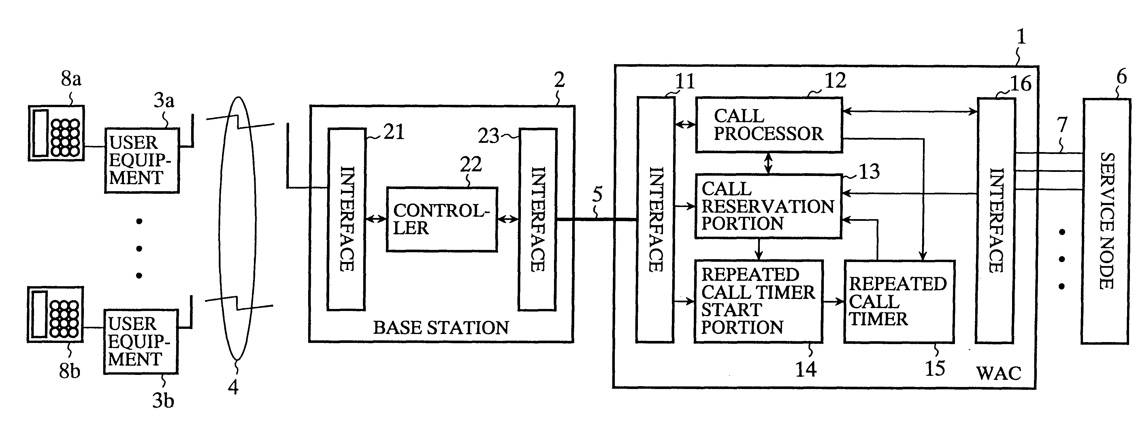
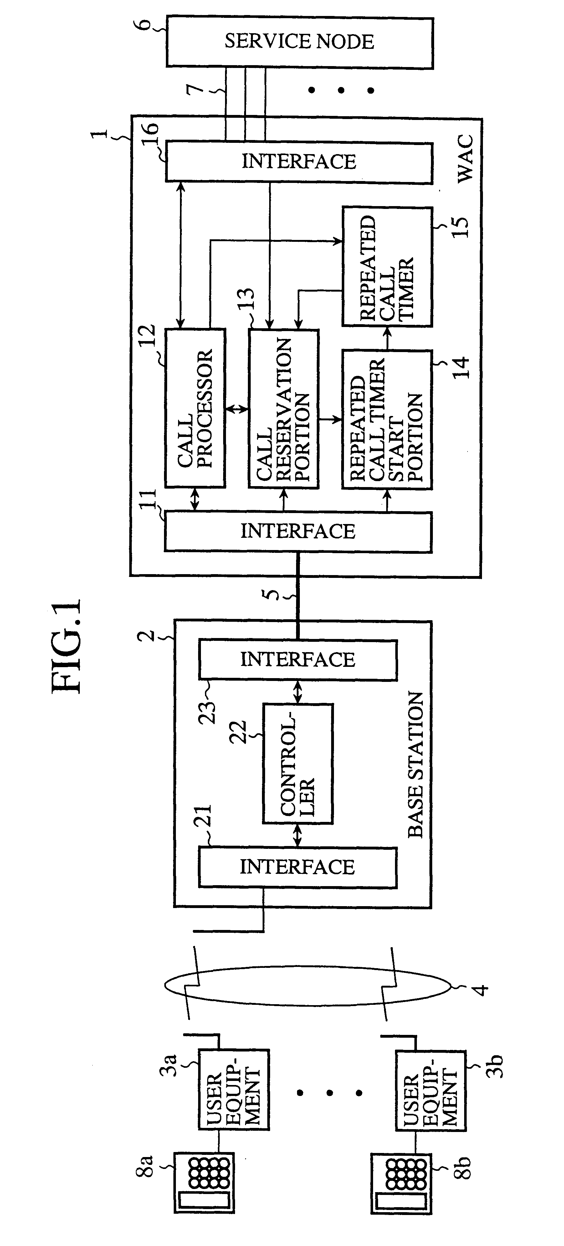
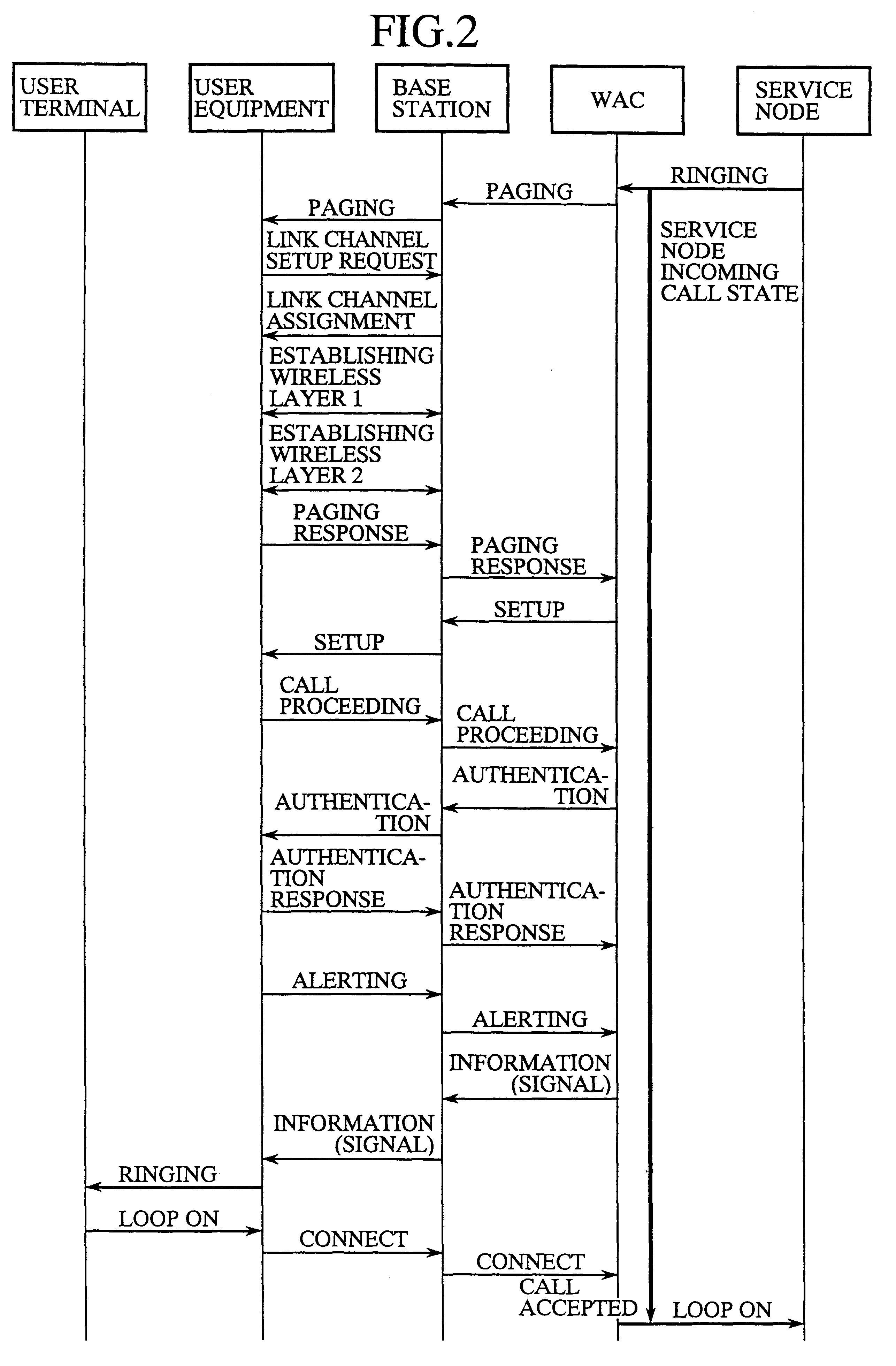
FIG. 3 is a sequence diagram illustrating the operation of the access network system in accordance with the present invention. When the WAC 1 receives a ringing (call request) from the service node 6, the call processor 12 of the WAC 1 sends a paging message to the called user equipment 3 via the base station 2. Receiving the paging message, the base station 2 transmits it to the user equipment 3 via the wireless circuit 4. Receiving the paging message from the base station 2, the user equipment 3 sends to the base station 2 a link channel setup request for requesting setup of a wireless channel between them.

If the interface 21 of base station 2 does not hold, when it receives the link channel setup message from the user equipment 3, i.e., a request for a wireless channel to be assigned, then the controller 22 sends to the user equipment 3 a link channel assignment rejection indicative of being unable to setup a wireless channel, and to the WAC 1 an idle wireless channel absent mess...

embodiment 2

FIG. 4 is a sequence diagram illustrating a second embodiment of the access network system in accordance with the present invention. The sequence is the same as that of FIG. 3 from the transmission of the ringing from the service node 6 to the WAC 1 up to the transmission of the idle wireless channel absent message from the base station 2 to the WAC 1 when the base station 2 cannot detect an idle wireless channel. When the WAC 1 receives the idle wireless channel absent message from the base station 2, the call reservation portion 13 of the WAC 1 sets the current incoming call in the call reservation state, and activates the repeated call timer 15 using a timer value stored in the repeated call timer start portion 14 in advance.

If the current subscriber line 7 of the service node is still in the incoming call state when the repeated call timer 15 completes counting, the call reservation portion 13 of the WAC 1 releases the call reservation state, and the call processor 12 carries ou...

embodiment 3

FIG. 5 is a sequence diagram illustrating the operation of a third embodiment of the access network system in accordance with the present invention. If the trunk line 5 between the WAC 1 and base station 2 that accommodates the called user equipment 3 is busy when the WAC 1 receives the ringing from the service node 6, the call reservation portion 13 of the WAC 1 sets the current incoming call in the reservation state, and the interface 11 of the WAC 1 starts idle channel monitoring to detect whether any channel in the trunk line 5 becomes idle. If the interface 11 of the WAC 1 detects an idle channel in the trunk line 5, the call reservation portion 13 releases the call reservation of the current incoming call, and the call processor 12 carries out the normal call processing as shown in FIG. 2, thereby achieving the incoming call successfully.

In the third embodiment, if the WAC 1 cannot obtain an idle channel in the trunk line 5 between the WAC 1 and base station 2 when the service...


PUM


Abstract

An access network system capable of reducing loss probability in an access network which is connected on one hand to a service node of an existing network through subscriber lines, and on the other hand to multiple user terminals, and has a concentrating function. A WAC (Wireless local loop Access Controller, that is, a controller of the access network) connected with the service node (local switch) receives from a base station a notification that no idle wireless channel is present if a wireless circuit is busy when the service node makes a call request, and receives from the base station a notification that an idle wireless channel is present when the base station detects it in the wireless circuit. If the WAC receives the channel busy notification, or cannot detect an idle channel in a trunk line, the WAC reserves a call processing. If the WAC receives the notification that an idle wireless channel is present, or detects an idle channel in the trunk line, and if the current subscriber line from the service node still holds the incoming call state, the WAC releases the reservation of the call processing, and performs a repeated call processing for the call request when the call request is still present.

Description

1. Field of the InventionThe present invention relates to an access network system that is connected to an existing local switch, includes a base station connected through a wireless circuit with fixed terminals such as user terminals installed in subscriber's houses, and is employed as an access network like a WLL (wireless local loop) with a function of concentrating user channels. Here, the access network refers to a network that connects the local switch of a caller with a called user, excluding the local switch and the user terminal themselves.2. Description of Related ArtFIG. 7 is a block diagram showing a configuration of a conventional access network like a WLL. In FIG. 7, the reference numeral 1 designates a WAC (WLL Access Controller) which is the controller of a WLL; and 2 designates a base station that is connected with the WAC 1 through a trunk line 5. The reference numerals 3a-3b each designate user equipment connected with the base station 2 through a wireless circuit...

Claims


Application Information

Patent Timeline
Patent Type & Authority Patents(United States)
IPC IPC(8): H04Q7/20H04Q7/38H04W72/06H04W84/14
CPCH04W84/14H04W72/06H04W72/563
Inventor IMAI, TAKESHINEMOTO, MASAAKIMATSUYAMA, HIROSHI
Owner MITSUBISHI ELECTRIC CORP
Why Eureka
Try Eureka