Evaporative emission control system for internal combustion engine

a technology of evaporative emission control and internal combustion engine, which is applied in the direction of electric control, combustion-air/fuel-air treatment, machines/engines, etc., can solve the problems of increasing the possibility of erroneous diagnosis, variable air/fuel ratio, and engine operation instability

Inactive Publication Date: 2001-04-24
NISSAN MOTOR CO LTD
View PDF6 Cites 25 Cited by
  • Summary
  • Abstract
  • Description
  • Claims
  • Application Information

AI Technical Summary

Problems solved by technology

However, the above described prior art evaporative emission control system is constructed so as to communicate the intake pipe directly with the fuel tank at the time of reducing the pressure in the above described conduit, so the fuel vapors in the fuel tank may possibly be drawn into the engine during the time of reducing the pressure in the conduit to cause a variation of the air / fuel ratio and therefore an unstable operation of the engine.
However, a high vehicle speed will increase the pressure in the conduit due to sloshing (i.e., splash of the fuel in the fuel tank causing variations of the fuel surface), thus increasing the possibility of erroneous diagnosis.
The prior art system is adapted to reduce the pressure in the conduit and make a leak diagnosis irrespective of the vehicle speed, and therefore cannot meet the above two requirements at the same time.

Method used


Image

  • Evaporative emission control system for internal combustion engine
  • Evaporative emission control system for internal combustion engine
  • Evaporative emission control system for internal combustion engine

Examples


Embodiment Construction

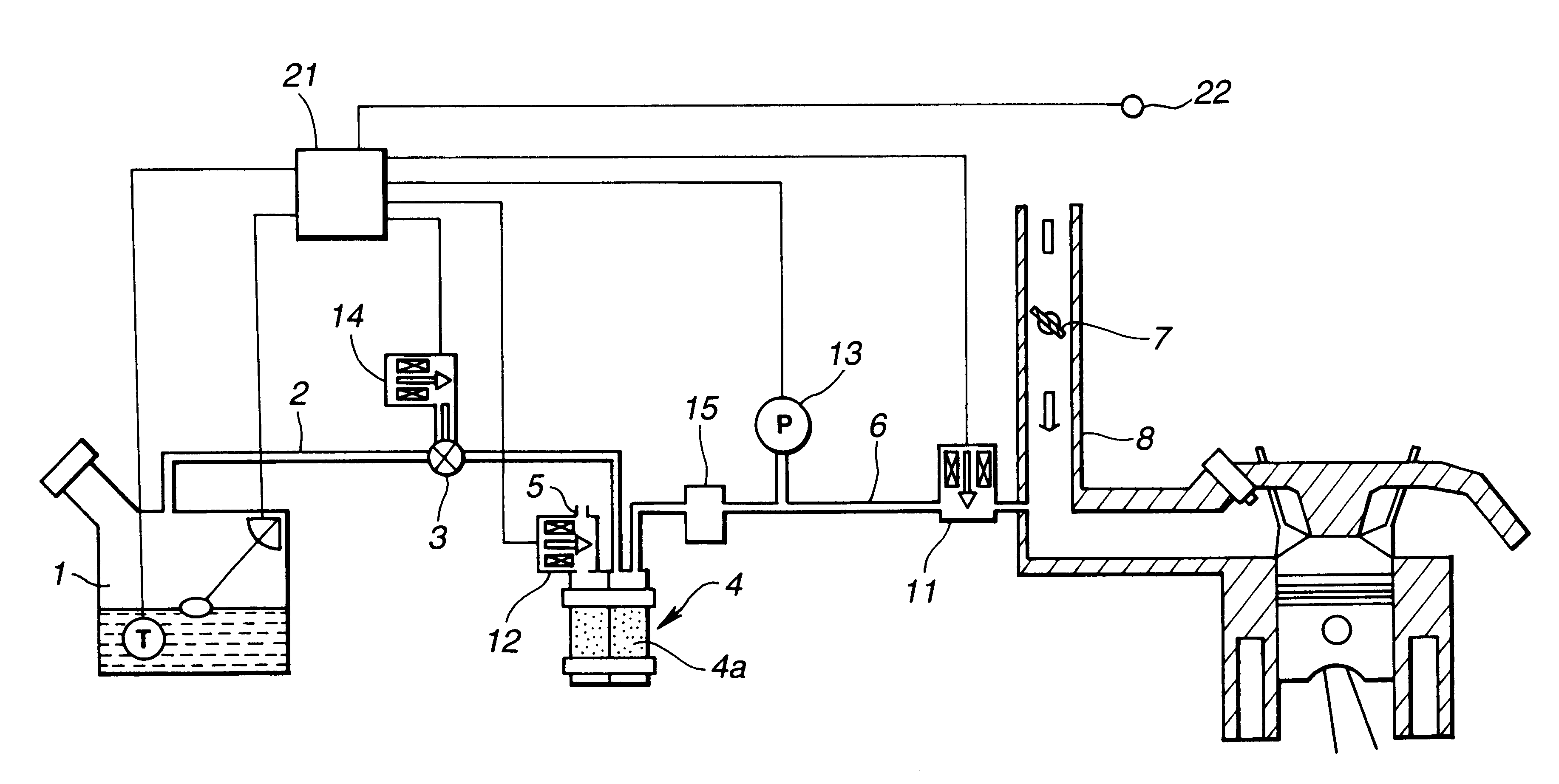
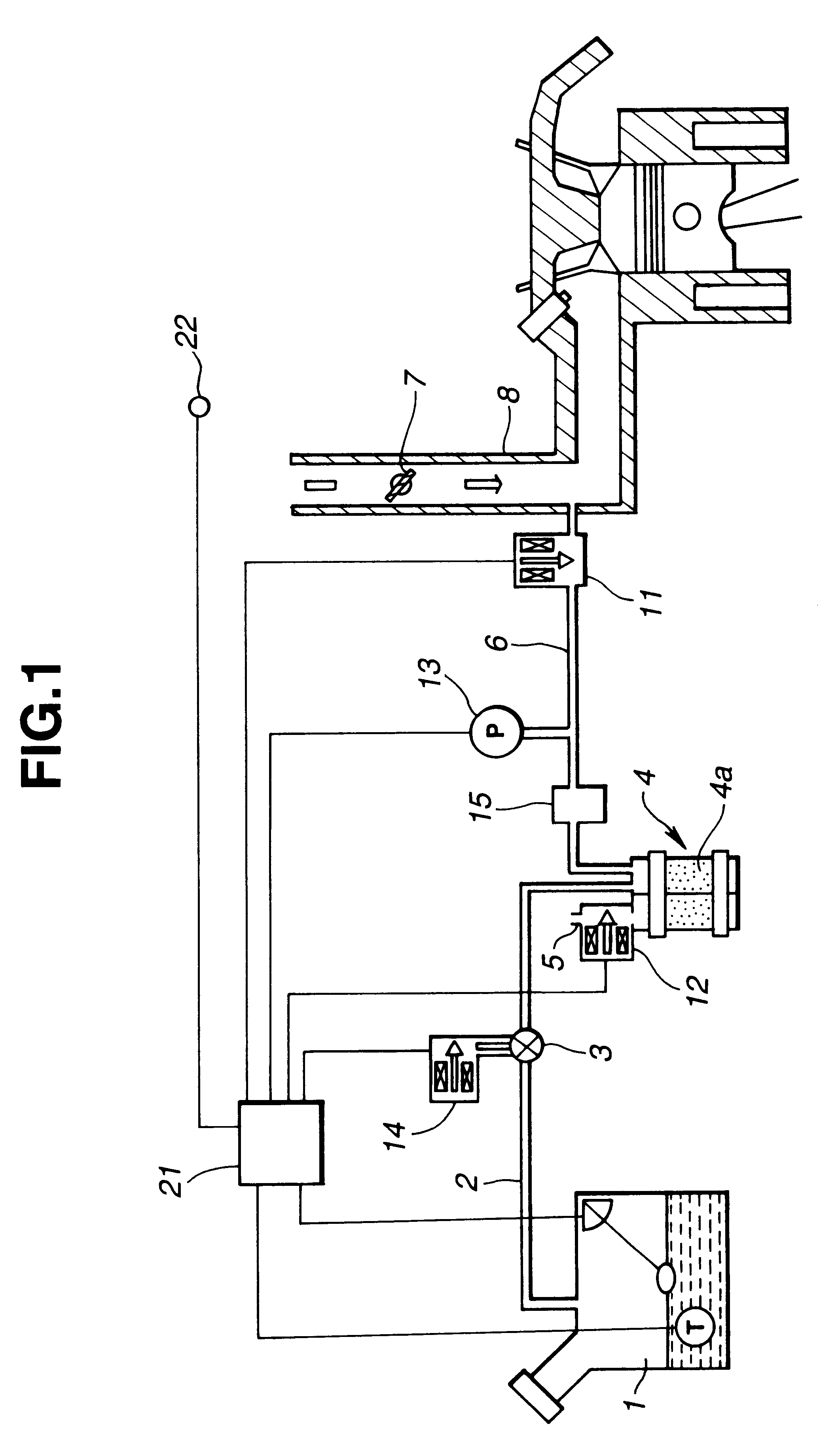
Referring first to FIG. 1, an evaporative emission control system for an internal combustion engine includes a canister 4, a conduit (first conduit) 2 providing communication between the canister 4 and a fuel tank 1 and a conduit (second conduit) 6 providing communication between the canister 4 and an intake pipe 8 portion downstream of a throttle valve 7 of an internal combustion engine.

On the conduit 2 are mounted a vacuum cut valve (check valve) 3 which is adapted to open when the pressure in the fuel tank 1 is lower than the atmospheric pressure and a bypass valve 14 in parallel with the vacuum cut valve 3. The bypass valve 14 is a normally closed valve and is driven by a step motor (not shown)so as to selectively open and close. The bypass valve 14 is adapted to open under a predetermine condition at the time of a leak diagnosis.

On the conduit 6 are mounted a purge control valve 11, a pressure sensor 13 for measuring the pressure in the conduit 6, and a vacuum tank 15 of a pred...


PUM


Abstract

An evaporative emission control system is provided which includes a bypass valve, purge control valve and a vent control valve. To make a leak diagnosis, firstly the vent control valve is closed while the purge control valve is opened, whereby to negatively pressurize the inside of a fuel vapor conduit portion extending from the bypass valve to an intake pipe side. After the pressure in the fuel vapor conduit portion from the bypass valve to the intake pipe is reduced to a predetermined value, the purge control valve is closed. Then, the bypass valve is opened, and after lapse of a predetermined time from the opening of the bypass valve a variation of pressure in a conduit extending from the fuel tank to the purge control valve is asured. Based on the variation of pressure, a leak diagnosis is made. By this, the evaporative emission control system can prevent the fuel vapor in the fuel tank from being drawn into the intake pipe during reduction of pressure in the conduit and thus causing unstable operation of an engine.

Description

1. Field of the InventionThe present invention relates in general to evaporative emission control systems for internal combustion engines, and more particularly to an evaporative emission control system of the type which is capable of making a leak diagnosis, i.e., capable of detecting if a leak is present in the evaporative control system.2. Description of the Related ArtAn internal combustion engine for current automotive vehicles includes an evaporative emission control system. The evaporative emission control system includes a canister containing activated charcoal to collect and store volatile fuel vapors from a fuel tank during the time the engine is not inning. The evaporative emission control system also includes a purge line or conduit connecting between an intake pipe portion downstream of a throttle valve and the canister. The purge line opens under a predetermined condition after start of the engine to draw fresh air into the canister and purge the canister. The collecte...

Claims


Application Information

Patent Timeline
Patent Type & Authority Patents(United States)
IPC IPC(8): F02M25/08F02D41/02G01M3/26
CPCF02M25/0809
Inventor KAWAMURA, KATSUHIKOKAWANO, AKIHIRO
Owner NISSAN MOTOR CO LTD
Why Eureka
Try Eureka