
Cooler housing apparatus and method of making the same

a technology of cooler housing and cooling housing, which is applied in the direction of lighting and heating apparatus, indirect heat exchangers, and stationary conduit assemblies, etc., can solve the problems of prior art creating danger, damage to the surface of the cooler housing, and the deficiencies of sophisticated examples of cooler housings, so as to increase the volume of water, reduce the chance of another object striking the assembly and damaging it, and increase the stability of the housing

Inactive Publication Date: 2001-05-01
PORT A COOL
View PDF39 Cites 11 Cited by
  • Summary
  • Abstract
  • Description
  • Claims
  • Application Information

AI Technical Summary

Benefits of technology

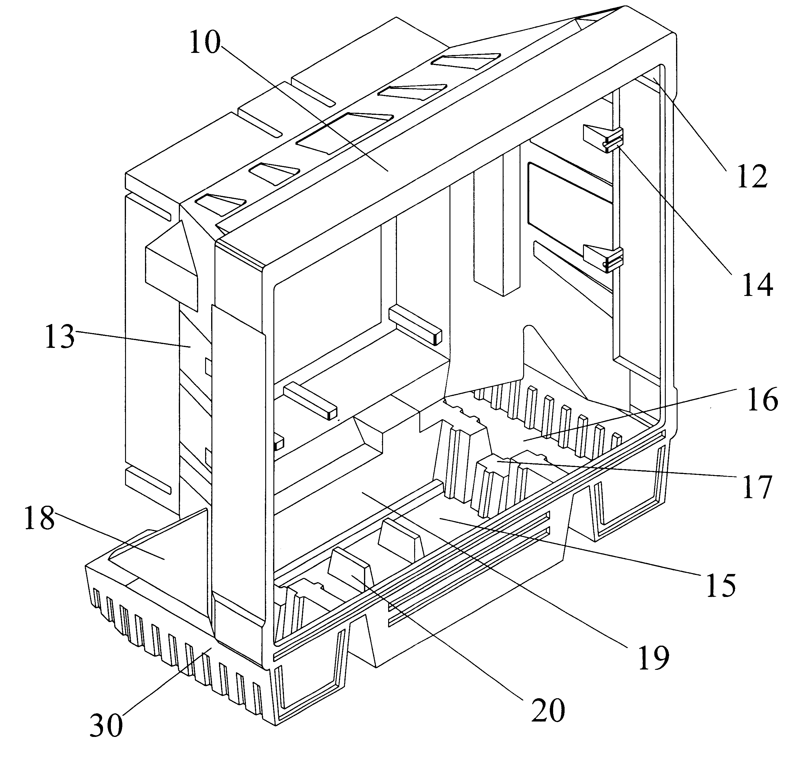
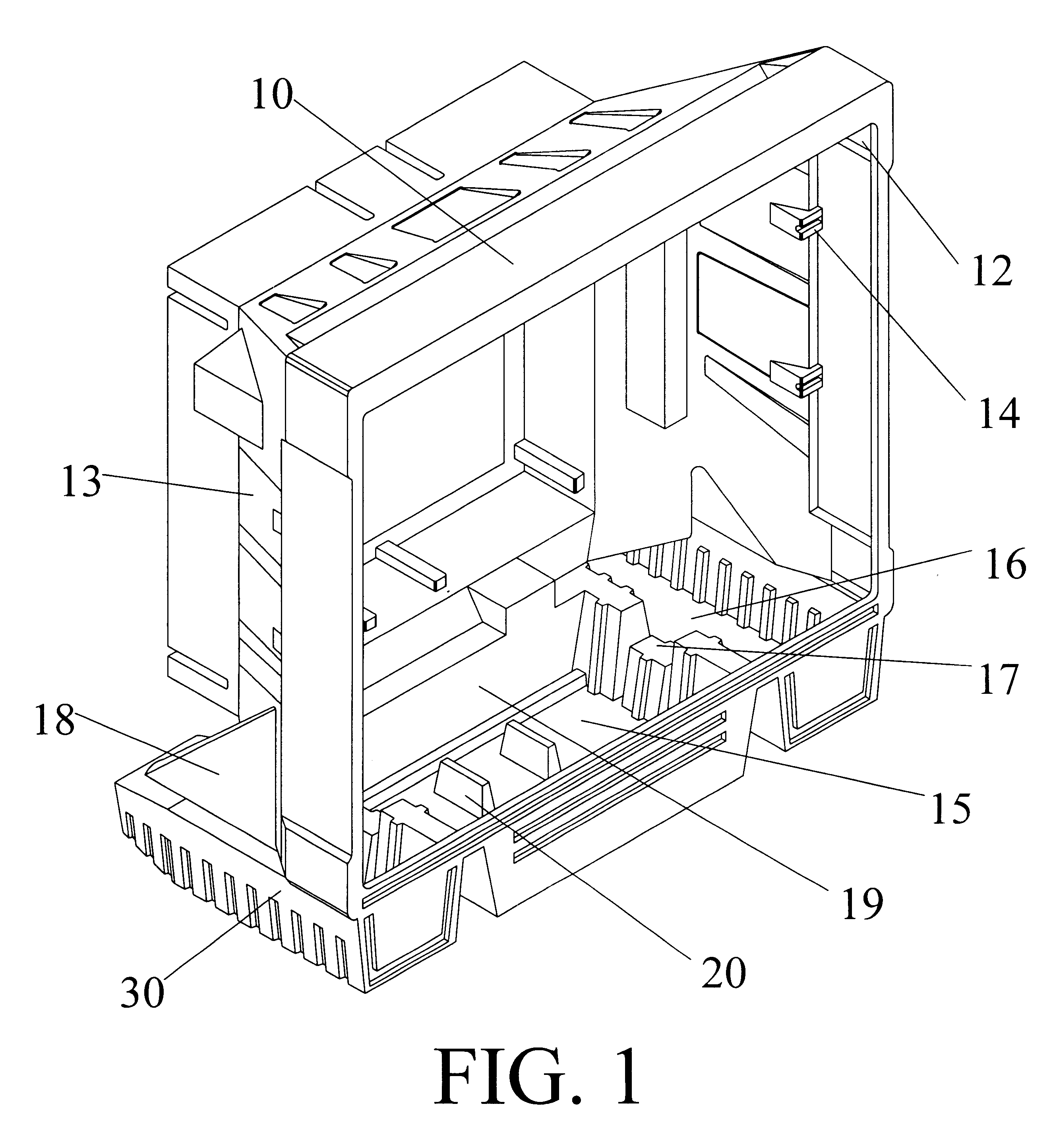
The housing preferably comprises at least one recess. Thus, the plumbing assemblies do not protrude from the overall silhouette of the housing. Further, when recessed, the chances of another object striking the assemblies and damaging them is significantly reduced.
Also, the housing comprises a plurality of braces attached to the interior of the housing and bracing the back plane of the pads when installed. This configuration offers the same protection as the guards or gratings that were used in the prior art, but these bars also provide a back support for the pads and keep them aligned within the housing. Additionally, the replacement of the pads can be accomplished without having to contend with removing the cumbersome grating or mesh required in the prior art.
Moreover, the sump tank of the present invention comprises a central base further comprising at least one additional cavity defined by the far edges of the unit, creating pontoon-like structures that extent to the bottom sides of the unit. This structure dramatically increase the volume of water that may be stored in the unit. This housing connects each cavity to the central collection chamber via channels in the bottom of the housing. These channels also provide a support frame. This support frame structure can be connected to wheels or casters that can be affixed or fitted to the housing. Because these pontoon-like structures and the support frame structure evenly distribute the weight of water around the entire bottom of the housing, rather than centralizing the entire weight. This distribution increases the stability of the housing. This stability is increased by a plurality of pylons that strengthen and support the housing by providing additional rigidity.
Finally, the present invention employs a plurality of ridges designed to prevent side to side movement of the pump contained therein. These ridges restrict any lateral movement of the pump. Additionally, the use of an aluminum bracket attached to the back wall of the housing and connected to the hose running from the pump further restricts movement of the pump in all directions. Thus, even the movement and jostling associated with shipping will not jar or displace the pump.

Problems solved by technology

Even these sophisticated examples of cooler housings cannot overcome some of the deficiencies of the prior art.
Bumping or brushing against a wall or other obstacle could damage these connections protruding from the surface of the housing.
The prior art also created a danger as the pads aged and deteriorated.
These gratings or guards hinder the replacement of the pads, however.
This central tank configuration limits the flexibility of the unit and unduly burdens the center of the housing with the entire weight of the water.
The flow valves attached to the slanted walls were typically inaccurate because the slant of these walls actually decreases the pressure needed to open the valve.
The movement of the housing during shipping or movement during use would upset the pump and affect performance.

Method used


Image

  • Cooler housing apparatus and method of making the same
  • Cooler housing apparatus and method of making the same
  • Cooler housing apparatus and method of making the same

Examples


Embodiment Construction

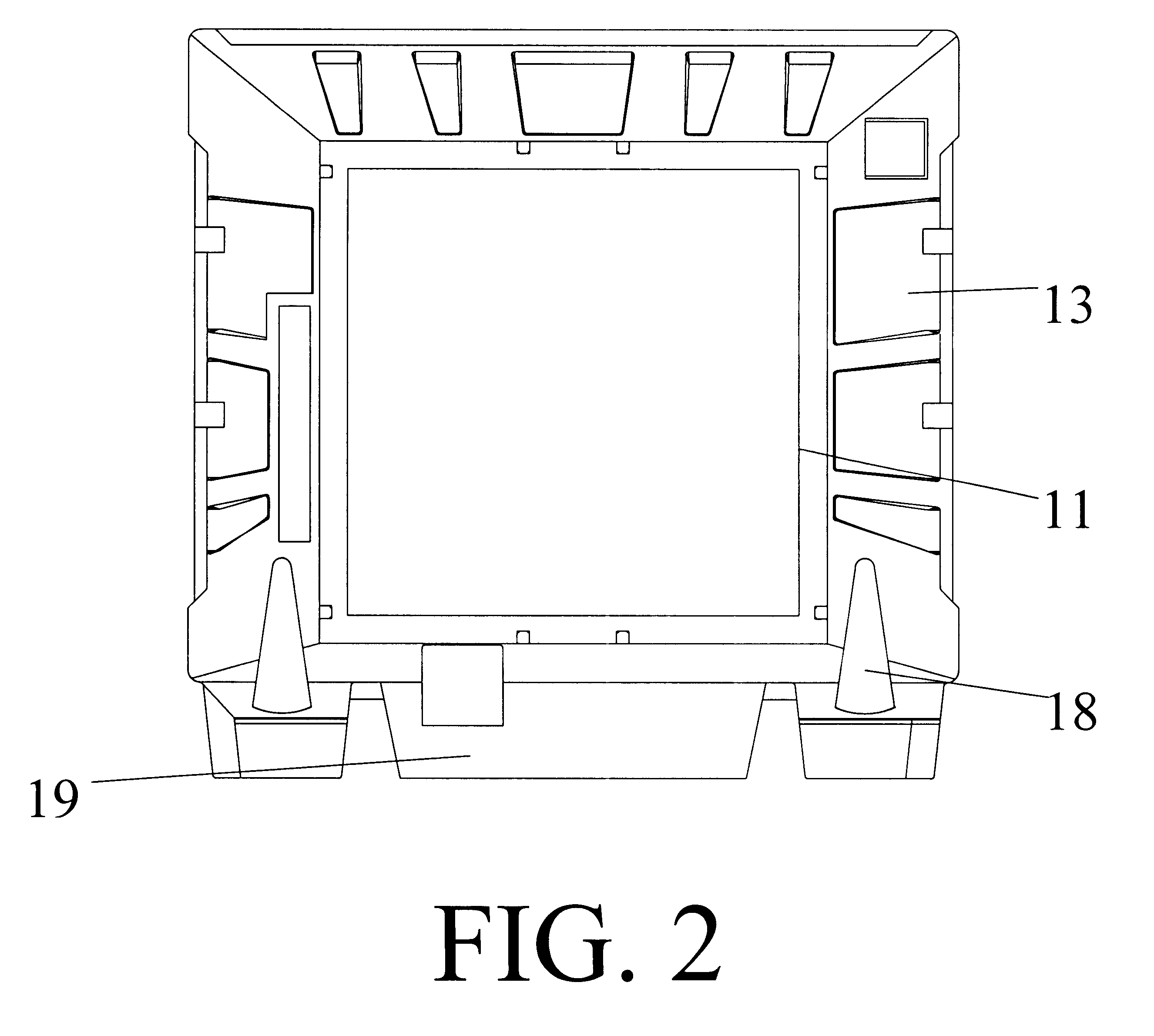
As depicted in FIGS. 1-4, the present invention comprises housing 10, having front opening 11 and rear opening 12, that may be used for encasing, protecting, and supporting components integral in providing air movement and / or relief from the heat. Though the preferred embodiment envisions the use of housing 10 as an integral part of the portable evaporative cooler, housing 10 can provide support and protection for the components of nearly any cooler.

Housing 10 may be formed out of metal, plastic, composites, organic fibers including wood, or any other substance capable of being formed, molded, or otherwise shaped to include at least one aspect of the invention. Housing 10 is preferably formed by rotation molding or resin transfer process.

Referring to FIG. 1, housing 10 comprises a variety of features. Of particular interest, housing 10 comprises at least one recess 13 capable of strengthening housing 10 and offering a prime location for the placement and protection of plumbing assem...


PUM


Abstract

A cooler housing capable of encasing, protecting, and supporting cooler components, particularly components necessary for use as a portable evaporative cooler. Though the housing described herein may be used in cooling devices ranging from simple conventional fans to complex heat exchanger devices, the preferred embodiment of this invention is preferably used in conjunction with a portable evaporative cooler employing this housing and further comprising a motor that drives a pump connected to a sump tank.

Description

The present invention is related to a cooler housing that is used for encasing, protecting, and supporting the components that comprise a variety of cooling devices, particularly for use as the housing for portable evaporative coolers.Background of the InventionCooler housings are known in the art. Housings encase, protect, and support the numerous components that may be included within coolers. Additionally, the housing forms an integral part of the cooler by directing the air flow through the cooler. Numerous examples of housings for coolers exist in the prior art. For example, U.S. Pat. No. D362,905 issued Oct. 3, 1995, which is hereby incorporated by reference, depicts a representation of a sophisticated housing for a cooler. This housing provides an integral part of this portable evaporative cooler. Though housings may be employed in a variety of coolers, portable evaporative coolers comprise a variety of components that especially benefit from a strong, rigid, yet portable coo...

Claims


Application Information

Patent Timeline
Patent Type & Authority Patents(United States)
IPC IPC(8): F28D5/00
CPCF28D5/00
Inventor CALVERT, PHILLIP D.
Owner PORT A COOL
Learn More