Closure for container and closure package and method of making same

a technology of closure package and container, which is applied in the direction of closure using stoppers, liquid handling, applications, etc., can solve the problems of reducing the effectiveness of the seal, poor strip torque capability and leakage, and the potential of the container to leak past such sealing systems

Inactive Publication Date: 2001-05-01
KUBETECH CUSTOM MOLDING INC
View PDF17 Cites 26 Cited by
  • Summary
  • Abstract
  • Description
  • Claims
  • Application Information

AI Technical Summary

Benefits of technology

Accordingly, among the objectives of the present invention are to provide an improved liquid containing and dispensing package of the type employing a plug seal in a closure-and-container system, and of the type in which the closure has an externally threaded skirt received within an internally threaded container neck or finish, and wherein (1) the closure and container neck are constructed to create a plug seal fit with enough interference to create a positive seal and withstand the normally applied torque without stripping of the closure / container thread system, (2) sealing engagement force is directly proportional to screw-down force applied to the closure in reaching closed position on the container, (3) the closure seals and container cooperate to improve the centering of a multiple concentric array sealing system, (4) improved correction of any out-of-round condition of the container is effected during seal closure application, (5) the closure construction is readily adaptable to provision of multiple sequential seals of the liner type or V-ring type, final closure screw-down increases the torque required to cause the closure thread to strip past the container thread to thereby achieve high torque capability without danger of thread stripping, and improved removal torque capability is also achieved.
A further object is to provide an improved method of forming an improved plug seal between a plastic container and a plastic closure that is capable of achieving the aforementioned objectives while utilizing economical, mass production plastic molding techniques and equipment already available and that is readily adaptable to manufacture of a variety of closure-and-container systems utilizing plug-type seals.
At least one of the container and closure components is made of resiliently deformable plastic material, and preferably both the closure and container are made of plastic material, and the materials of the closure and container preferably differ in hardness relative to another, so that either the plug seal rib or the juxtaposed neck wall surface defonns under closure / container engaging forces to thereby enhance the sealing capability and life.
Preferably, the closure is injection molded in one piece from plastic material so that the trapping flange comprises an annular innermost wall portion integrally joined to the closure skirt that protrudes radially outwardly and also is inclined upwardly (in the container package storage orientation) and thus away from said closure threads. The trapping flange also is formed with a radially outwardly extending wall portion integrally joined with the flange inner wall portion that radially overlaps the container neck open upper edge in assembly. The flange conical portion is formed by a conical skirt wall portion integrally dependent from the radial wall portion that sealing cam wedge embraces the neck open upper edge and creates increasing squeeze force as the closure is threaded into the neck wall. Preferably the plug seal rib is integrally formed on the flange inner wall portion.
In one embodiment, the container neck wall is provided with a circumferentially continuous internal groove disposed between the neck internal threads and neck open upper edge for receiving the closure plug seal rib by interference snap fit when said closure is threaded into the wall and reaches closed position thereon to thereby enhance removal torque capability.

Problems solved by technology

With such prior art DBS containers with cup / cap closures or with such child resistant safety closures, low viscosity products and pressure building products packaged in the container have the potential to leak past such sealing systems due to a number of factors.
In the case of a plug-type seal on the closure, using a plastic container having an internal thread cooperating with an external thread on the plastic closure has in the past led to poor strip torque capability and leakage over time due to material creep.
Providing an interference fit of the plug seal of the closure tends to push the container neck wall away from the plug, thereby reducing the effectiveness of the seal.
Also, use of a plug-type seal in of itself may not provide sufficient torsional resistance in the fully closed and sealed position of the closure on the container to prevent the closure thread from stripping past the container thread under excessive, but often typical, hand applied final closure tightening force.

Method used


Image

  • Closure for container and closure package and method of making same
  • Closure for container and closure package and method of making same
  • Closure for container and closure package and method of making same

Examples


first embodiment

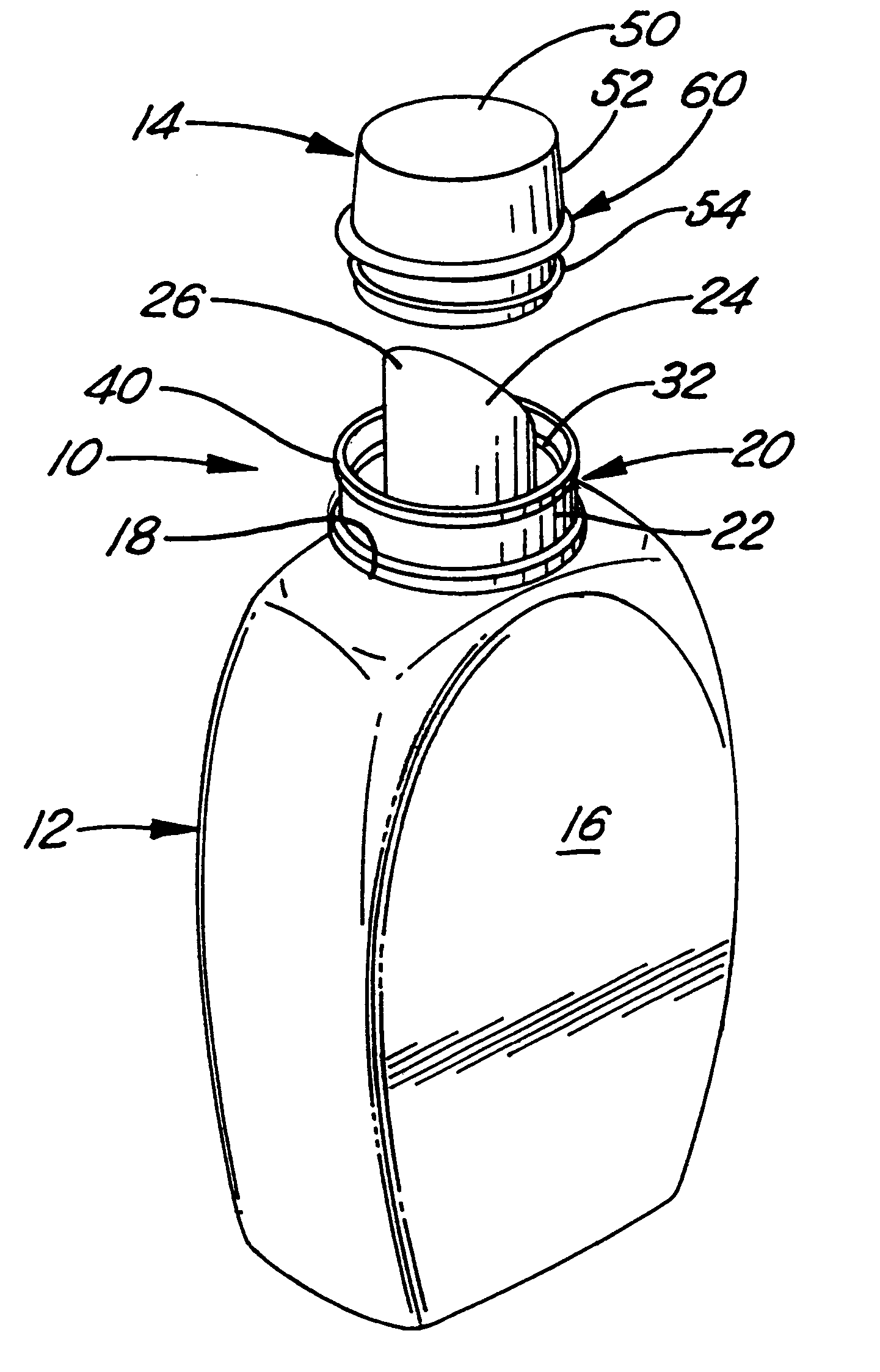
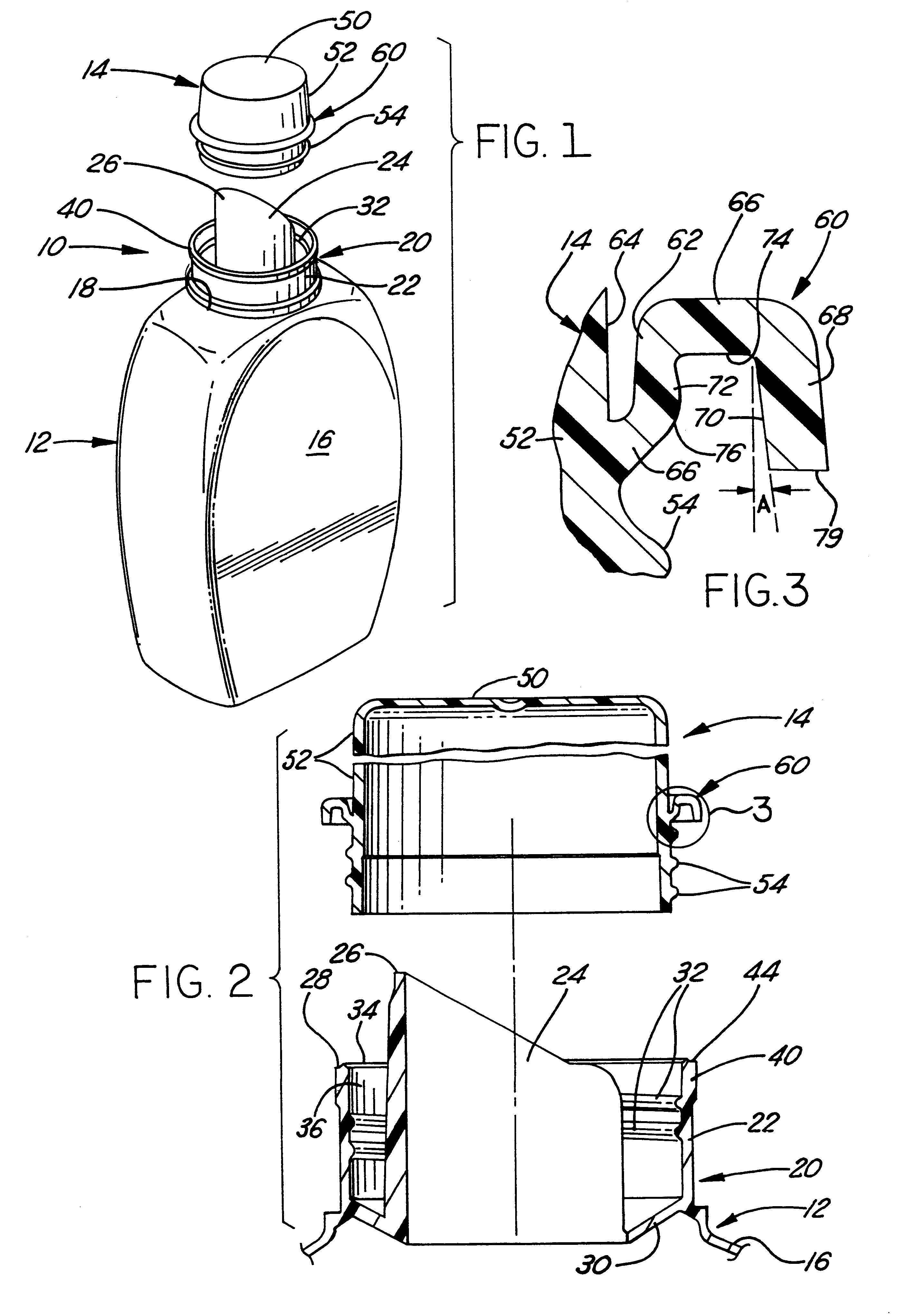
In accordance with the invention shown in FIGS. 1-4, a closure-and-container package 10 is shown in FIG. 1 that, by way of example, is of the self-draining DBS type that comprises a plastic bottle 12 specifically designed for liquids and which may be constructed in accordance with the disclosure of the aforementioned Krall U.S. Pat. No. 5,207,356. The package also includes a removable combination cap and dispensing cup type closure 14 designed for removable threaded attachment to container 12.

Container 12 includes a hollow body portion 16 which terminates at its upper end in an opening 18 through which the contents of the container 12 can be dispensed. A dispensing portion 20 extends from and communicates with body portion 16 and includes a circular cylindrical wall or collar 22 which extends angularly around body opening 18. A dispensing spout 24 is located within and is encircled by collar 22 and includes an upper end pouring lip 26 which extends above the uppermost free end edge ...

second embodiment

DETAILED DESCRIPTION OF THE SECOND EMBODIMENT

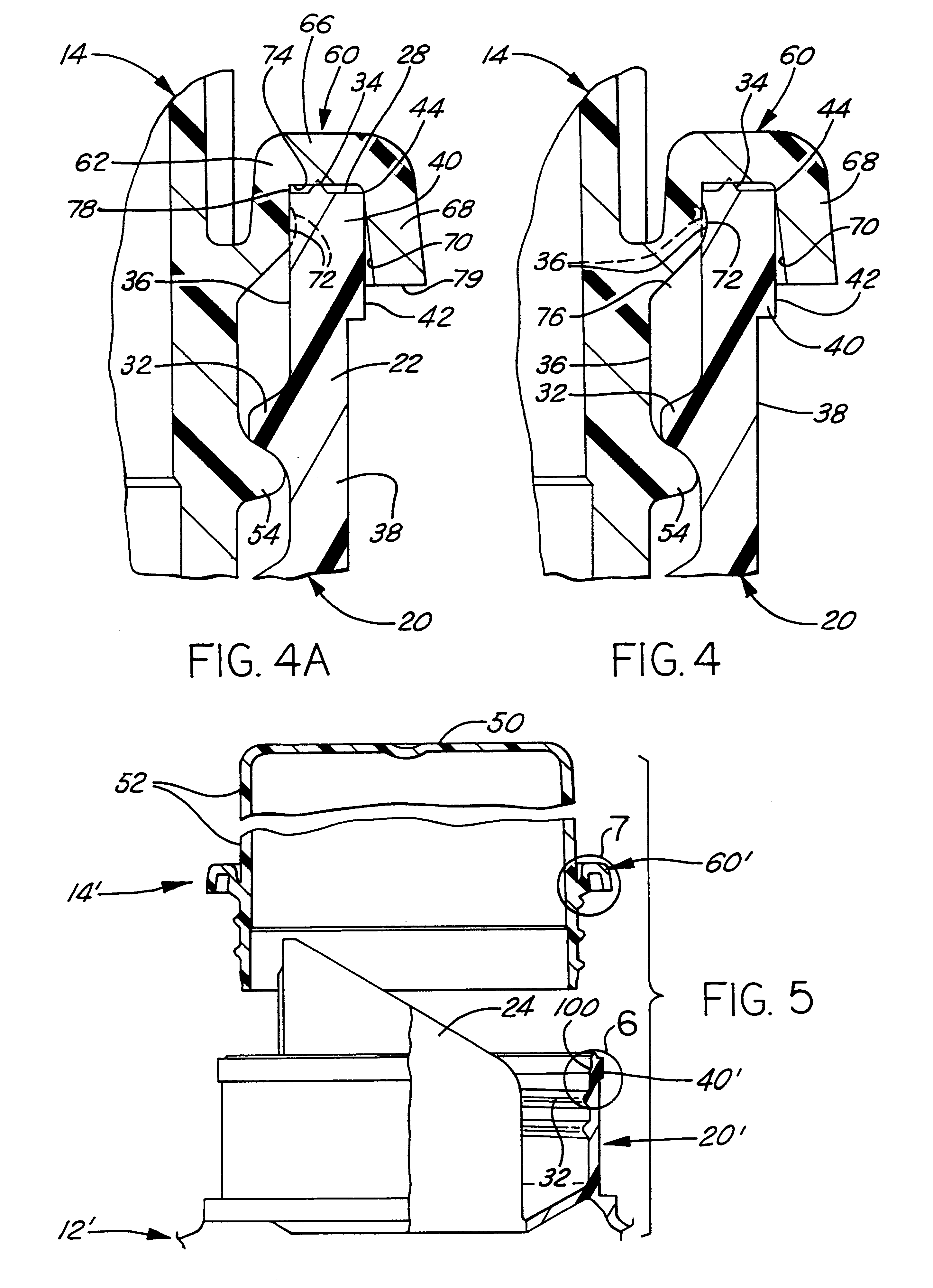
FIGS. 5-8 illustrate a second embodiment of the closure-and-container sealing system of the invention wherein like elements are given like reference numerals and their description not repeated, and those elements alike in fimction are given the same reference numerals raised by a prime suffix. In this embodiment, the finish of the container is provided with an annular circumferentially continuous internal groove 100, best seen in FIG. 6, at a predetermined design location in interior surface 36 axially between the uppermost tum of thread 32 and the upper end surface 28 of head 40. Closure 14' is identical to closure 40 except that the trapping flange 60' is provided with the circular sealing plug rib 72' having a suitably modified contour, and being made of a deformable material with sufficient resilience to be resiliently yieldably deformed during downward travel of flange 60' relative to head 40' to enable it to be squeezed radially inw...


PUM


Abstract

A closure for a container-and-closure sealing system embodied in a container and closure package, and method of making the same. The container has an open mouth surrounded by a cylindrical neck wall having internal threads and an open upper edge. The closure is a cap / dispensing cup type and has a skirt with external threads adapted for threaded receipt within the container neck wall. A circumferentially continuous flange projects outwardly from the skirt and has a conical portion adapted for cam engaging, trapping and sealing with the open upper edge of the neck wall as the closure is threaded into this wall. The closure skirt also has a circumferentially continuous plug-type sealing surface that extends radially outwardly from the skirt between the trapping flange and closure external threads adapted for interference sealing engagement with the neck wall as the closure is threaded thereinto. The materials of the closure and container may differ in hardness relative to another so that either the plug seal rib of the juxtaposed neck wall surface deforms under closure / container engaging forces to thereby enhance the sealing capability and life. The flange has a conical skirt wall portion integrally dependent from a flange radial wall portion that is adapted to sealing cam wedge embrace the neck open upper edge and creates increasing squeeze force as the closure is threaded into the neck wall. A concentrically intermediate annular seal is also provided in the form of V-rib or liner material interposed in assembly between the container upper edge and the flange radial wall portion. The container neck wall may have a circumferentially continuous internal groove disposed between the neck internal threads and open upper edge for receiving the closure plug seal rub by interference snap fit when the closure is threaded into the wall and reaches closed position thereon to thereby enhance removal torque capability.

Description

This invention relates to liquid containing and dispensing packages, and more particularly to DBS container-and-closure packages which include a pouring spout and a removable closure that also functions as a measuring cup.In one widely-used commercial type of liquid containing and dispensing package incorporating a drainback system (DBS), a pouring spout is positioned on the neck of the container, either as part of a drip-catching apron fitment or integrally molded with the container body, and a closure in the form of a combined cap and dispensing cup is removably threadably interengaged with the periphery of the container neck or spout fitment.For example, Krall U.S. Pat. No. 5,207,356 (incorporated herein reference) shows a plastic liquid containing and dispensing package which comprises a plastic blow molded container having a body portion which terminates at its upper end in an integrally formed dispensing portion that extends from and communicates with the body portion. The dis...

Claims


Application Information

Patent Timeline
Patent Type & Authority Patents(United States)
IPC IPC(8): B65D39/08B65D39/00B65D43/10
CPCB65D39/08
Inventor GEISINGER, GREGORY A.TREPINA, GEORGE R.HAFFNER, EUGENE F.KIDD, MARK R.
Owner KUBETECH CUSTOM MOLDING INC
Why Eureka
Try Eureka