Fuel filter for engine

a technology for fuel filters and engines, applied in the direction of steam power plants, separation processes, vessel construction, etc., can solve the problems of affecting the affecting the service life of the engine, and putting the fuel tank on the deck without any protection,

Inactive Publication Date: 2001-05-01
SANSHIN KOGYO CO LTD
View PDF4 Cites 28 Cited by
  • Summary
  • Abstract
  • Description
  • Claims
  • Application Information

AI Technical Summary

Benefits of technology

It is, therefore, another object to provide a fuel filter whereby accumulated water therein can be checked easily.
It is, therefore, a further object to provide a fuel filter wherein a water level is accurately sensed with a water detection mechanism even there is vibration in the engine.

Problems solved by technology

However, the fuel tank is likely to be laid on a deck without any protection against the water invasion.
The water mingled with the fuel may not only exert undesirable influence to engine operation but also jeopardize engine life.
Thus, the direct cylinder injected engine is not compatible with water mingled with fuel.
In the meantime, marine engines, particularly an outboard motor, easily generate much vibration.
One of the reasons is that the outboard motor is arranged to be detachable from a hull of a watercraft and hence it cannot be very strictly fixed thereto.
Due to the much vibration, conventionally, water in fuel is likely to be mixed up with the fuel and both of the water and the fuel are hardly separated from each other during the engine is running.
However, this check usually compels the operator to take an unnatural position because the operator should approach the fuel filter from the watercraft.
However, as described above, there is much vibration in the engine.
Also, room or a space for the fuel filter is generally small in the engine if it is for an outboard motor.

Method used


Image

  • Fuel filter for engine
  • Fuel filter for engine
  • Fuel filter for engine

Examples


Embodiment Construction

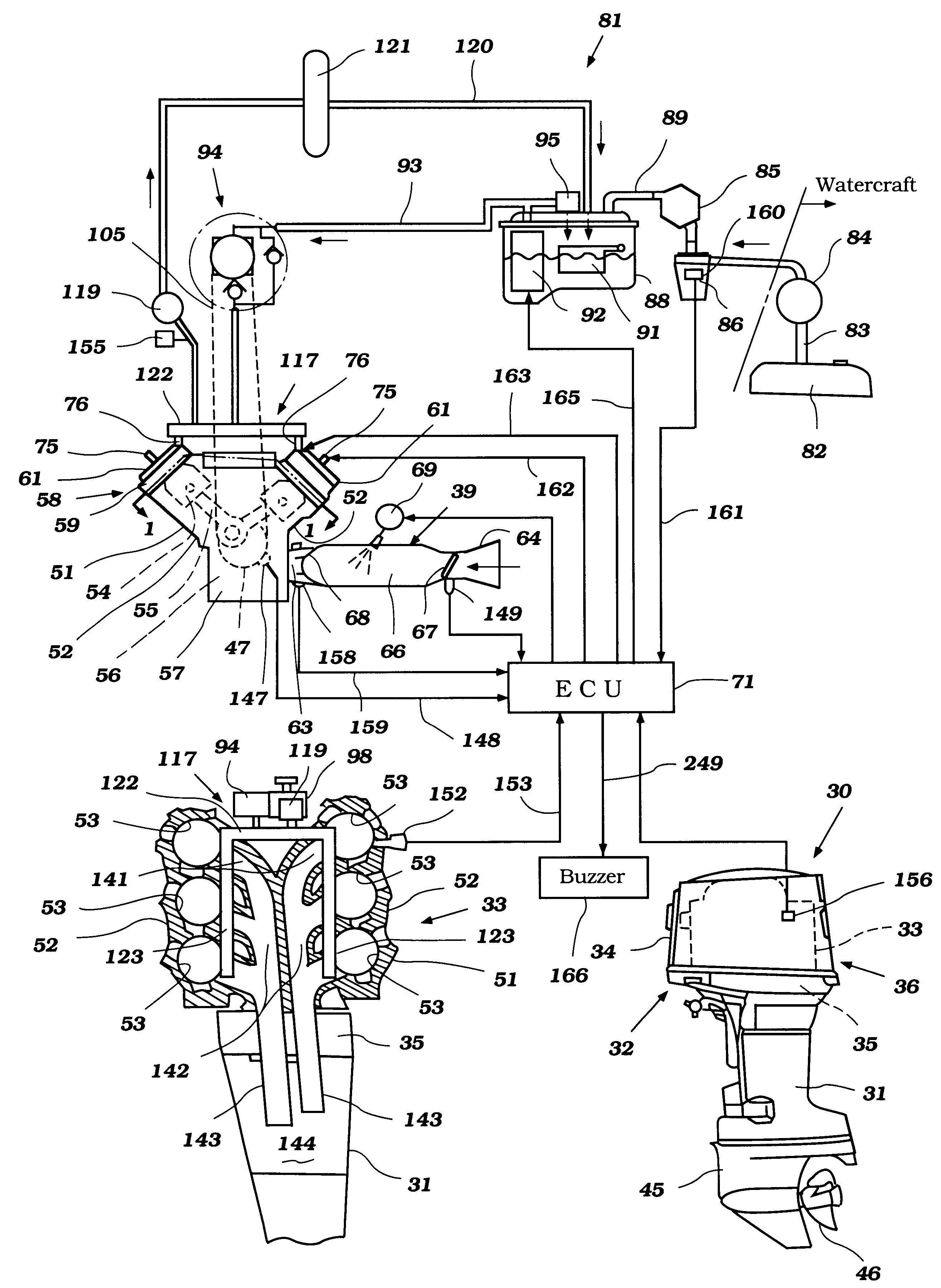
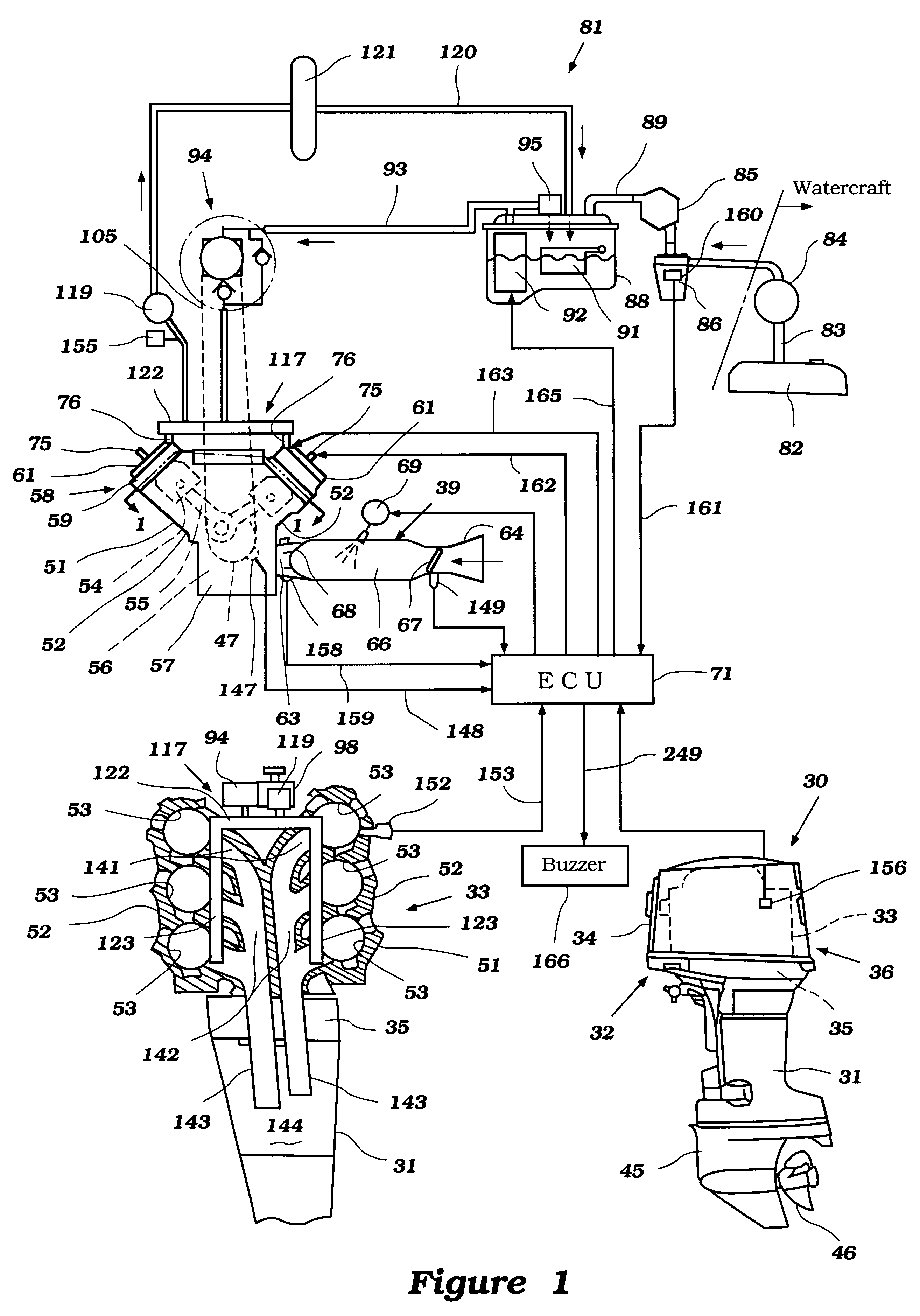
The general overall environment in which the invention is practiced and certain details of the engines will be described primarily by reference to FIG. 1 and additionally to FIGS. 2 and 3.

In the lower-right hand view of the FIG. 1, an outboard motor constructed and operated in accordance with an embodiment of the invention is depicted in side elevational view and is identified generally by the reference numeral 30.

The entire outboard motor 30 is not depicted in that the swivel bracket and clamping bracket that are associated with the driveshaft housing, indicated generally by the reference numeral 31, are not illustrated. This is because these components are well known in the art and the specific method by which the outboard motor 30 is mounted to the transom of an associated watercraft is not necessary to permit those skilled in the art to understand or practice the invention.

The outboard motor 30 includes a power head, indicated generally by the reference numeral 32, that is posit...


PUM

PropertyMeasurementUnit
non-sounding timeaaaaaaaaaa

Abstract

A fuel filter for an internal combustion engine suitable for detecting water accumulated therein. The fuel filter has a holder that is mounted on the engine and holds a filter body. A vessel is detachably affixed to the holder. There is a space between the end of the filter body and the bottom of the vessel. An inlet and outlet are provided for inducing fuel into and discharging it from the vessel. The inlet and outlet are connected relative to each other through the filter body for admitting flow of the fuel. In one feature of this invention, a water detection mechanism is placed under the filter body in the vessel. In another feature of this invention, the vessel is made of a transparent material. In a further feature, the holder is mounted on the engine via a damping member.

Description

1. Field of the InventionThis invention relates to a fuel filter for an engine and more particularly to a fuel filter for separating water from fuel contained therein and is most suitable to a marine engine.2. Description of Related ArtAt the present time, a large number of engines are used for marine application such as an outboard motor and a stem drive system. A fuel supply system is provided for supplying fuel to the engine. For example, a fuel tank is a first component of the fuel supply system for an engine of an outboard motor and it is located generally in a watercraft with which the outboard motor is associated. The other components of the fuel supply system, except a manually operable fuel pump, are placed on the engine that is accommodated in the outboard motor.In the meantime, the fuel supply components for marine engines are situated under relatively rigorous conditions. Particularly, circumambient water can break into them unless any protection is given. The components...

Claims


Application Information

Patent Timeline
Patent Type & Authority Patents(United States)
IPC IPC(8): F02B61/00F02B61/04F02M37/22F02M37/00F02B75/00F02B75/22F02B75/18B63H20/00
CPCF02B61/045F02M37/007F02M37/221F02B75/22F02B2075/1824B01D36/005F02M37/28F02M37/32
Inventor SATO, TAKAYUKIMOTOSE, HITOSHI
Owner SANSHIN KOGYO CO LTD
Why Eureka
Try Eureka