Dust caps for use with telecommunications adapters and connectors

a technology for telecommunications adapters and connectors, applied in the field of dust caps, can solve the problems of dust entering into the tip, no surface, and no style, and achieve the effect of reducing the diameter and preventing the contamination of the tip

Inactive Publication Date: 2001-05-08
SIEMON
View PDF6 Cites 470 Cited by
  • Summary
  • Abstract
  • Description
  • Claims
  • Application Information

AI Technical Summary

Benefits of technology

The above-discussed and other drawbacks and deficiencies of the prior art are overcome or alleviated by the dust caps of the present invention. A first embodiment of the invention is a dust cap for use with ST adapters, ST connectors and SC connectors. The dust cap includes a sealing surface for contacting the bottom of an ST adapter for sealing the portion of the adapter containing the alignment sleeve. The dust cap also includes an opening having a reduced diameter to prevent contamination of the tip of the ferrule of an ST or SC connector. The dust cap may be formed in a duplex fashion and include a retaining strap for securing the dust cap to an ST adapter. An alternative embodiment of the invention is a dust cap having a first side for mating with either an SC or ST adapter and a second side for mating with either an SC or ST connector.

Problems solved by technology

These styles are difficult to install and equally difficult to remove. FIG. 1A is a cross sectional view of a conventional dust cap 12 mounted to an ST adapter 10.
First, the dust cap 12 is generally cylindrical and does not provide any surface for gripping the dust cap during removal.
Accordingly, dust can ingress into the inside of the ST adapter and deteriorate performance of the optical fiber coupled at the adapter 10.
Conventional SC dust caps are effective dust caps, but are typically difficult to install and to remove. FIG. 1B is a perspective view of a conventional SC dust cap mounted to an SC adapter 13.

Method used


Image

  • Dust caps for use with telecommunications adapters and connectors
  • Dust caps for use with telecommunications adapters and connectors
  • Dust caps for use with telecommunications adapters and connectors

Examples


Embodiment Construction

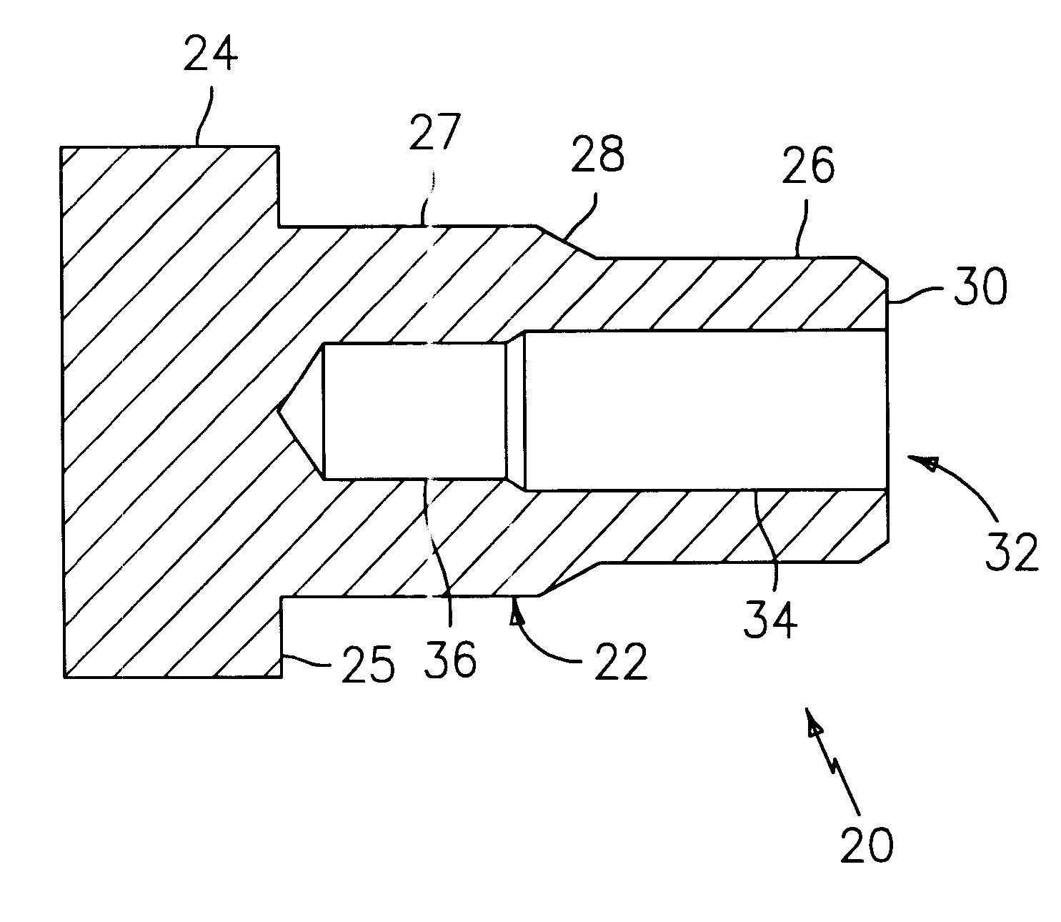
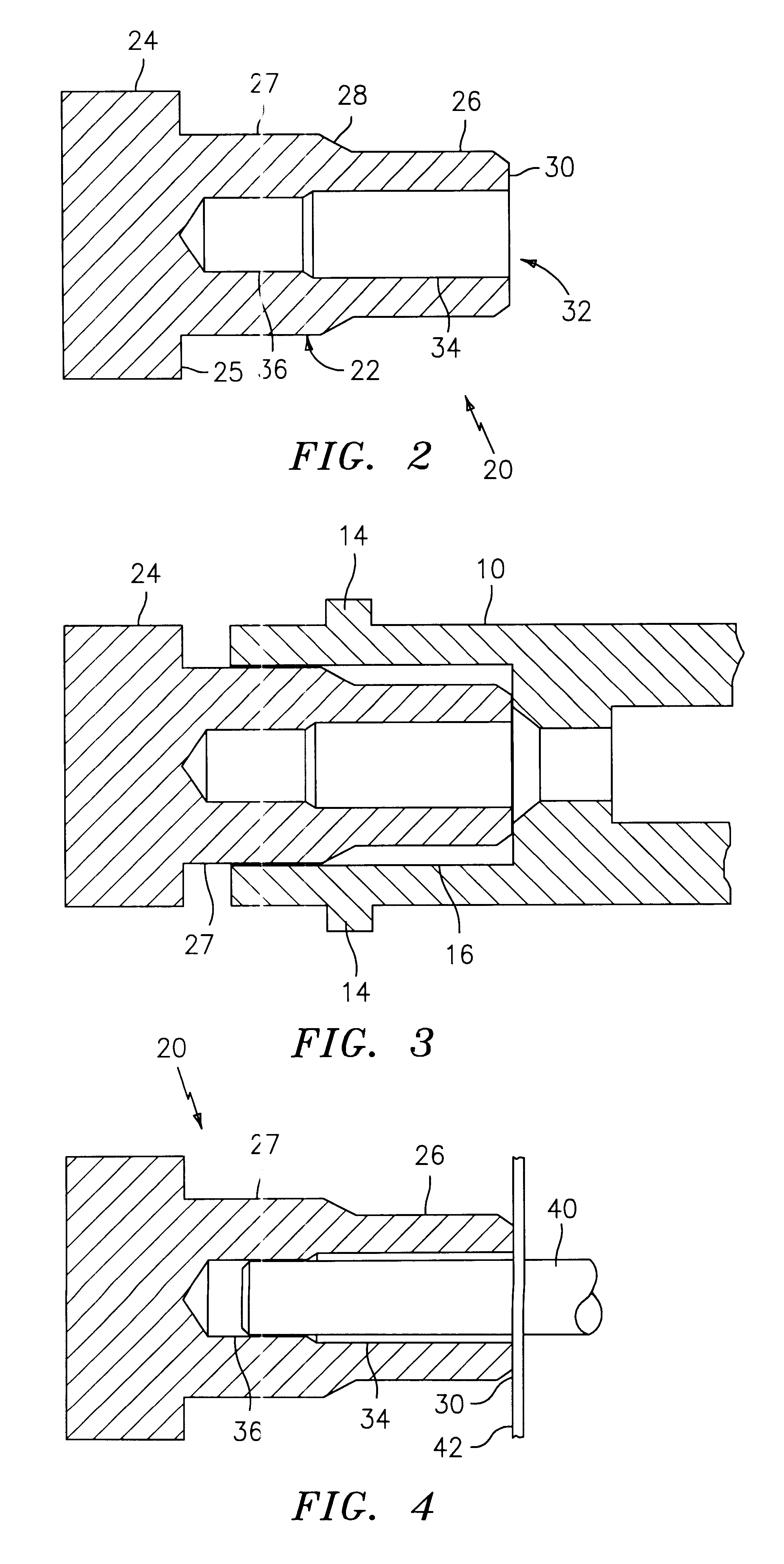
FIG. 2 is a cross-sectional view of a dust cap, shown generally at 20, having a body 22. A first end of body 22 is integrally joined to a dust cap head 24. Dust cap head 24 is generally cylindrical and has a diameter greater than body 22. It is understood that dust cap head 24 may have other geometries as long as an outer dimension is greater than the diameter of body 22. This provides a shoulder 25 for grasping dust cap 20 and facilitates installation and removal of the dust cap. The body 22 includes a first cylindrical section 27 and a second cylindrical section 26. The second cylindrical section 26 has a diameter less than the first cylindrical section and provides a lead in upon installing the dust cap 20. A tapered section 28 provides the transition between first cylindrical section 27 and second cylindrical section 26. The second end of body 22 has a sealing face 30 for contacting a surface in the ST adapter as shown in FIG. 3.

As shown in FIG. 3, the dust cap 20 fits within th...


PUM


Abstract

Dust caps for use with multiple optical fiber adapters and connectors. A first embodiment of the invention is a dust cap for use with ST adapters, ST connectors and SC connectors. The dust cap includes a sealing surface for contacting the bottom of an ST adapter for sealing the portion of the adapter containing the alignment sleeve. The dust cap also includes an opening having a reduced diameter to prevent contamination of the tip of the ferrule of an ST or SC connector. The dust cap may be formed in a duplex fashion and include a retaining strap for securing the dust cap to an ST adapter. An alternative embodiment of the invention is a dust cap having a first side for mating with either an SC or ST adapter and a second side for mating with either an SC or ST connector.

Description

BACKGROUND OF THE INVENTION1. Field of the InventionThe invention relates generally to dust caps and in particular to dust caps for use with multiple types of telecommunications adapters and connectors.2. Prior ArtDust caps are used to prevent optical fiber adapters and connectors from being contaminated by dust, dirt, etc. Most existing adapter manufacturers utilize an industry-standard, soft-polymer dust cap for ST adapters and a flat-surfaced, rectangular dust cap for SC adapters. These styles are difficult to install and equally difficult to remove. FIG. 1A is a cross sectional view of a conventional dust cap 12 mounted to an ST adapter 10. Conventional ST dust caps have several drawbacks. First, the dust cap 12 is generally cylindrical and does not provide any surface for gripping the dust cap during removal. In addition, the ST adapter includes keying posts 14 which prevent the dust cap 12 from making a good seal against the adapter body. Accordingly, dust can ingress into the...

Claims


Application Information

Patent Timeline
Patent Type & Authority Patents(United States)
IPC IPC(8): G02B6/38
CPCG02B6/3849G02B6/3878H01R13/5213
Inventor OTT, CONRAD L.VOLANSKY, EDWARD J.
Owner SIEMON
Why Eureka
Try Eureka