Signal transmission system and method for supervising the same

a transmission system and transmission method technology, applied in the field of transmission system and transmission method for supervising the same, can solve the problems of affecting the deterioration of transmission quality, undesirable non-linear effect of optical transmission lines, and difficulty in having a wide system margin for the whole system, and achieve the effect of large system margin

Inactive Publication Date: 2001-05-08
HANGER SOLUTIONS LLC
View PDF3 Cites 160 Cited by
  • Summary
  • Abstract
  • Description
  • Claims
  • Application Information

AI Technical Summary

Benefits of technology

According to a second aspect of the invention, an optical transmission system includes interface units that detect predetermined estimation parameters from the optical transmitter, the repeater and the optical receiver. The optical transmission system includes a simulator that simulates the transmission quality of the system in response to the estimation parameters supplied from the interface units. The simulator also controls each of the optical transmitter, the repeater and the optical receiver so as to minimize a bit-error rate or to maximize a Q-factor.

Problems solved by technology

If it does, it is difficult to have a wide range of system margin for the whole system.
However, in response to the high power input light, an undesirable non-linear effect is generated in the optical transmission line.
Such a non-linear effect influences deterioration of transmission quality.
In this situation, when an output power of the optical amplifier is changed, it gets more difficult to have enough range of system margin.

Method used


Image

  • Signal transmission system and method for supervising the same
  • Signal transmission system and method for supervising the same
  • Signal transmission system and method for supervising the same

Examples


first preferred embodiment

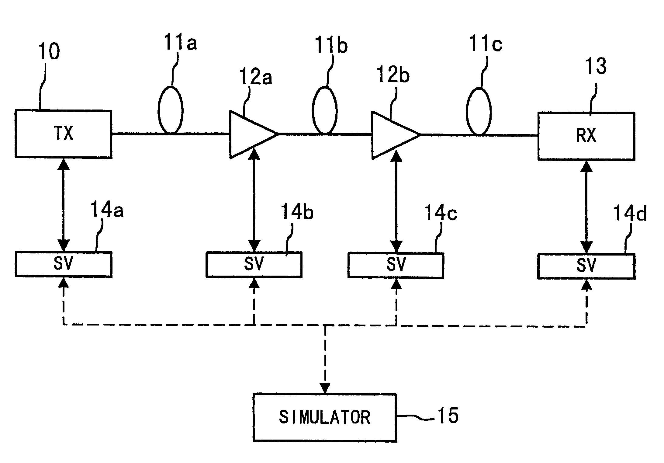
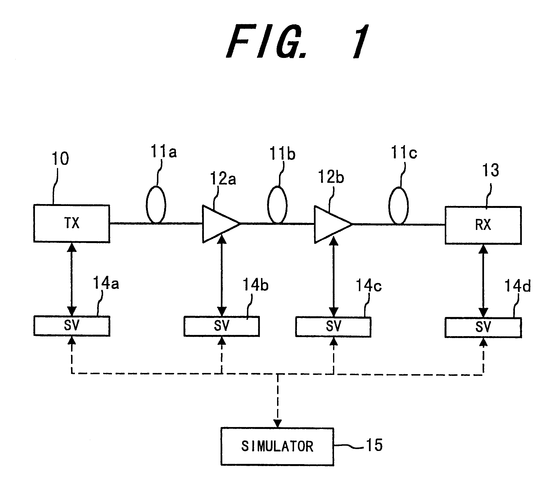
FIG. 1 shows the outline of an optical transmission system using an optical transmission simulator, according to a first preferred embodiment of the invention. In this system, a plurality of EDFAs (Erbium-Doped Fiber Amplifier) are employed as optical amplifiers.

In FIG. 1, the optical transmission system includes an optical transmitter (TX) 10, optical fibers 11a, 11b and 11c, repeaters 12a and 12b, an optical receiver (RX) 13, interface units 14a, 14b, 14c and 14d and an optical simulator 15. Each repeater is equipped with an optical amplifier, which amplifies a light signal. The optical fiber 11a connects the optical transmitter 10 and the repeater 12a. The optical fiber 11b connects repeaters 12a and 12b. The optical fiber 11c connects the repeater 12b and the optical receiver 13. The interface units 14a, 14b, 14c and 14d are connected to the optical transmitter 10, the repeater 12a, the repeater 12b and the optical receiver 13, respectively. Each of the interface units (SV) 14a,...

second preferred embodiment

FIG. 12 shows an optical transmission system, which performs automatic detection / control using a supervisory network. The system is provided with optical fiber amplifiers of EDFA (Erbium-Doped Fiber Amplifier).

The optical transmission system includes a transmitter / receiver 110, a repeater 120, a workstation (WS) 130, which automatically collects estimation parameters (source data) from each device to control the devices using the supervisory network.

The transmitter / receiver 110 and the repeater 120 are connected with transmission lines 100a and 100b of optical fibers, which transmit both of two main signal lights and a supervisory light. The main signal lights are wavelength-multiplexed to be transmitted in the both directions in the optical fibers 100a and 100b.

The transmitter / receiver 110 includes optical amplifiers 111a and 111b; optical couplers 112a and 112b, which divide a light by wavelength and direction; an E / O converter 113; an O / E converter 114, interface units (SV) 115a ...

third preferred embodiment

FIG. 13 shows the outline of an optical transmission system using an optical transmission simulator, according to a third preferred embodiment of the invention. In this preferred embodiment, the same or corresponding components to the first preferred embodiment are indicated by the same symbols.

In FIG. 13, the optical communication system includes an optical transmitter (TX) 10; an optical transmission line, including optical fibers 11a, 11b and 11c; repeaters 12a and 12b; an optical receiver (RX) 13, which receives the light signal; interface units (SV) 14a, 14b, 14c and 14d; and simulators 15a, 15b, 15c and 15d.

The optical fiber 11a connects the optical transmitter 10 and the repeater 12a. The optical fiber 11b connects the repeaters 12a and 12b. The optical fiber 11b connects the repeater 12b and the optical receiver 13. The interface unit 14a is connected between the optical transmitter 10 and the simulator 15a. The interface unit 14b is connected between the repeater 12a and th...


PUM


Abstract

A signal transmission system includes an interface unit that monitors the operating condition of each device. The signal transmission system also includes a simulator that simulates the transmission quality of the system in response to the operating condition of each device, and controls each device so as to optimize the transmission quality.

Description

This application claims the priority of Applications No. H09-109248, filed Apr. 25, 1997 in Japan, and No. H10-019222, filed Jan. 30, 1998 in Japan, the subject matters of which are incorporated herein by reference.The present invention relates to a signal transmission system and a method for supervising the same, and more particularly, to an optical transmission system and a method for supervising the same using a simulator.In the recent years, an optical transmission system using an optical amplifier, which directly amplifies a light signal without converting it it into an electric signal has been increasingly employed. For increasing the amount of light signals to be transmitted through a single optical amplifier, a wavelength multiplex type and a two-way transmission type of optical amplifiers have been proposed. Such an optical amplifier directly amplifies a light signal in analog fashion using an excitation light without converting it the light signal into an electric signal. ...

Claims


Application Information

Patent Timeline
Patent Type & Authority Patents(United States)
IPC IPC(8): H04B10/08H04B10/032H04B10/07H04B10/071H04B10/077H04B10/079H04B10/2507H04B10/2525H04B10/2537H04B10/2563H04B10/294H04B10/297
CPCH04B10/0775H04B10/0777H04B10/0779H04B10/0795H04B10/07951H04B10/07953H04B10/07955H04B10/07957H04B10/0797H04B10/0799H04B10/2537H04B2210/077
Inventor SATO, HIDEAKIASABAYASHI, ISSEIMAEDA, HIDENARIWATANABE, TAKASHI
Owner HANGER SOLUTIONS LLC
Why Eureka
Try Eureka