
Thermoelectric system

a technology of thermoelectric system and generator, which is applied in the direction of electric winding, instruments, and high-voltage converters, can solve the problems of ineffective use of generated power from thermoelectric power generator, repeated operation of voltage-up converter, and inability to precisely measure the thermal electromotive force while load is in operation, so as to facilitate effective utilization of generated power energy.

Inactive Publication Date: 2001-05-15
CITIZEN WATCH CO LTD
View PDF8 Cites 54 Cited by
  • Summary
  • Abstract
  • Description
  • Claims
  • Application Information

AI Technical Summary

Benefits of technology

It is an object of the present invention to solve the above-described disadvantages in a thermoelectric system, to facilitate effective utilization of generated power energy from the thermoelectric power generator while compensating for the influence of the Peltier effect on the generated voltage of the thermoelectric power generator, even when the Peltier effect occurs as a result of power supply from the thermoelectric power generator to a load means.
The configured thermoelectric system allows the measured thermal electromotive force to be compensated when influenced by the reduction of generated voltage due to the Peltier effect, which occurs when the continuously supplied electric power to the load means, by thermoelectric power generator is not negligible, so as to control supply and suspension of power to the load, assuming voltage as corresponding to the generated voltage originally expected. Accordingly, a thermoelectric system which can effectively utilize the generated power of the thermoelectric power generator even when the Peltier effect is created, and makes the most of the power which can be generated by the thermoelectric power generator, can be realized without being affected by the Peltier effect.

Problems solved by technology

However, in the conventional thermoelectric system, temporary reduction of the thermal electromotive force caused by the Peltier effect is not considered, and the temporary reduction of the thermal electromotive force is merely considered to be the result of a temperature change in the outside circumstances.
Therefore, if the thermoelectric system is configured to switch between operation and suspension of the voltage-up converter in accordance with the magnitude of the generated voltage of the thermal power generating device as above, there exists a disadvantage that the voltage-up converter repeatedly performs the operation and the suspension when the value of the generated voltage is close to the detection threshold value.
That is, when a thermoelectric system is configured to switch between supply and suspension of power to a connected load in accordance with the value of generated power from a thermoelectric power generator, it becomes impossible to precisely measure the thermal electromotive force while the load is in operation.
As a result, there may be cases where generated power from the thermoelectric power generator can not be used effectively.

Method used


Image

  • Thermoelectric system
  • Thermoelectric system
  • Thermoelectric system

Examples


Embodiment Construction

Embodiments of the thermoelectric system according to the present invention will be explained in detail with reference to drawings hereinafter.

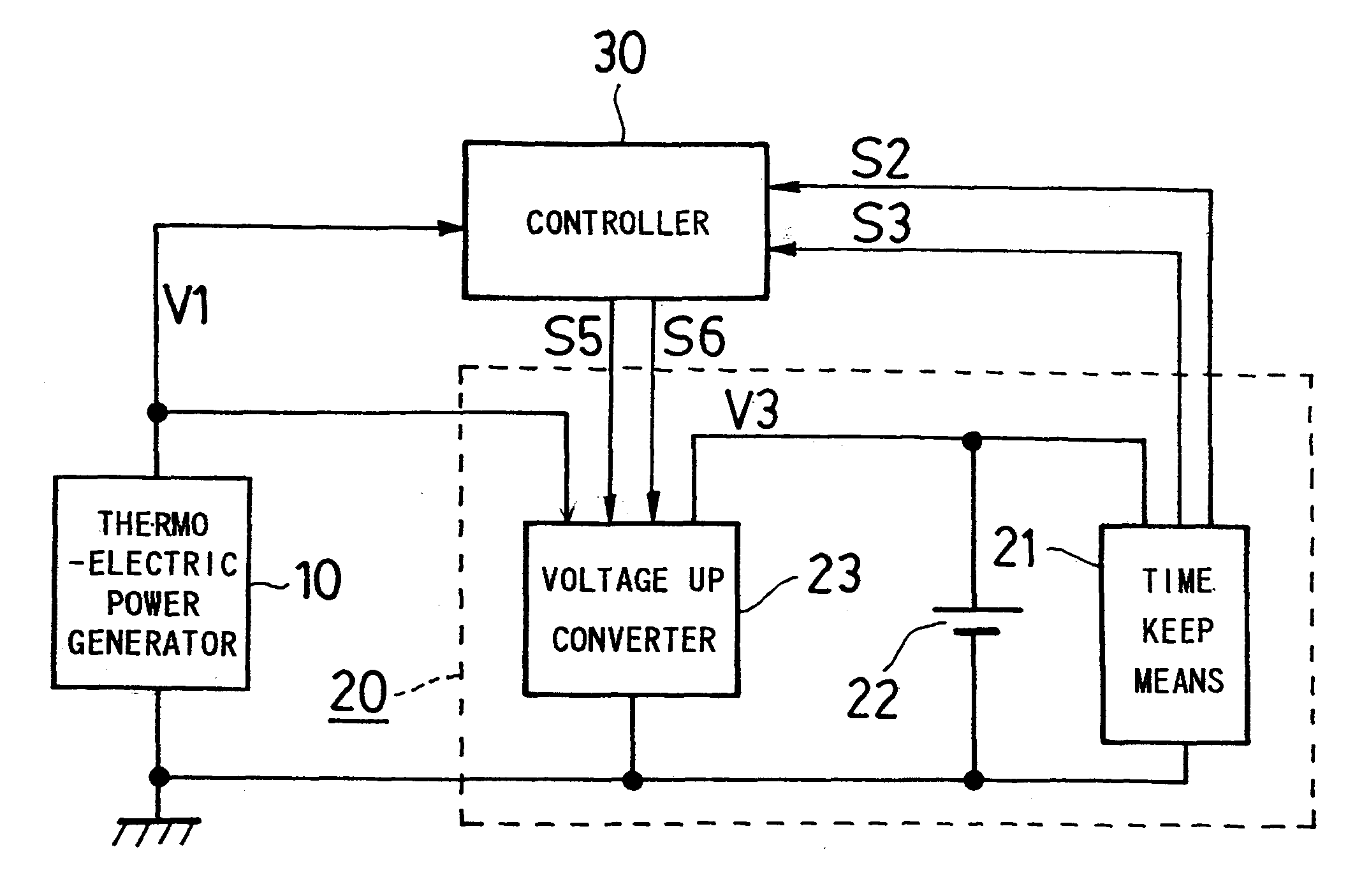
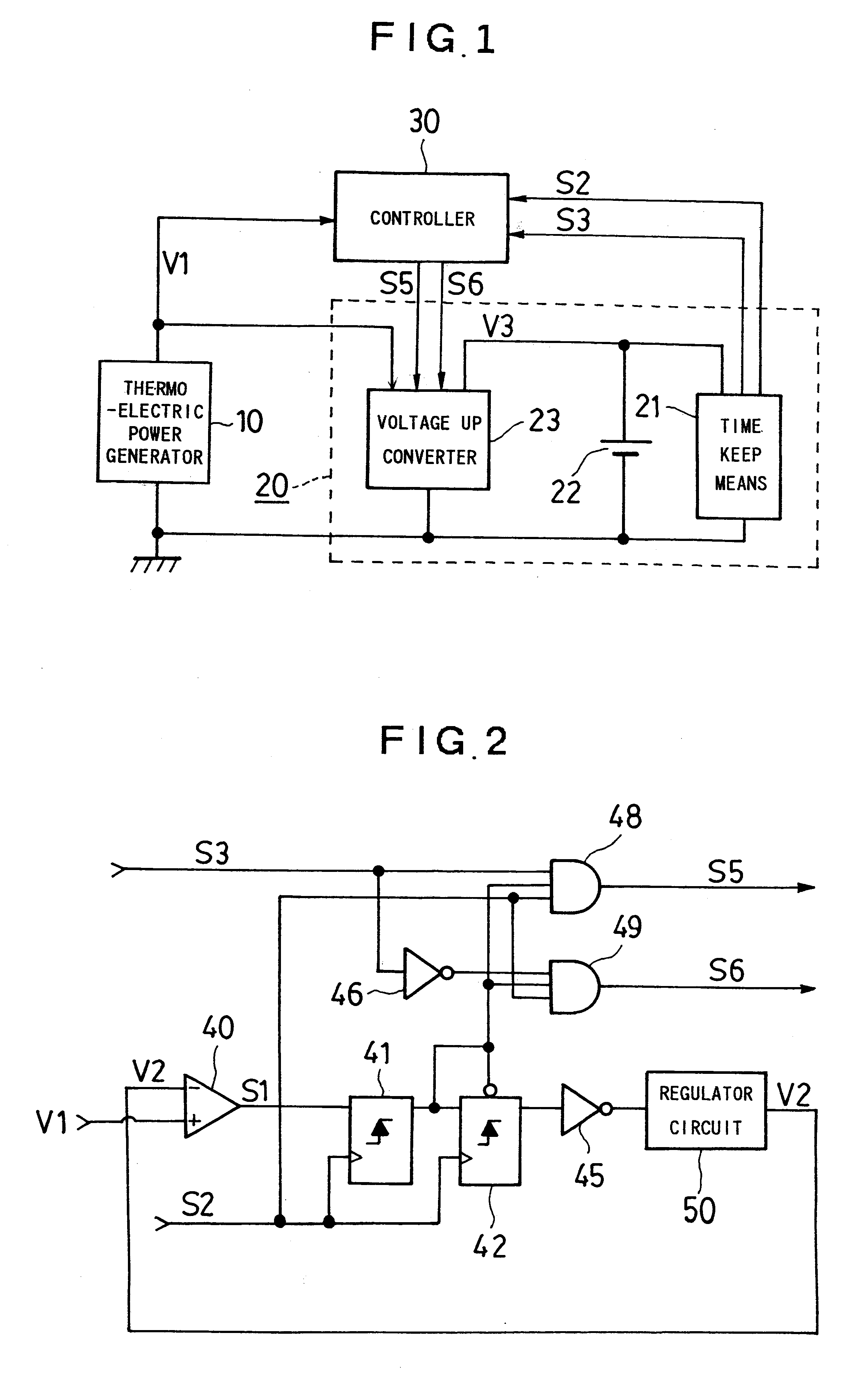
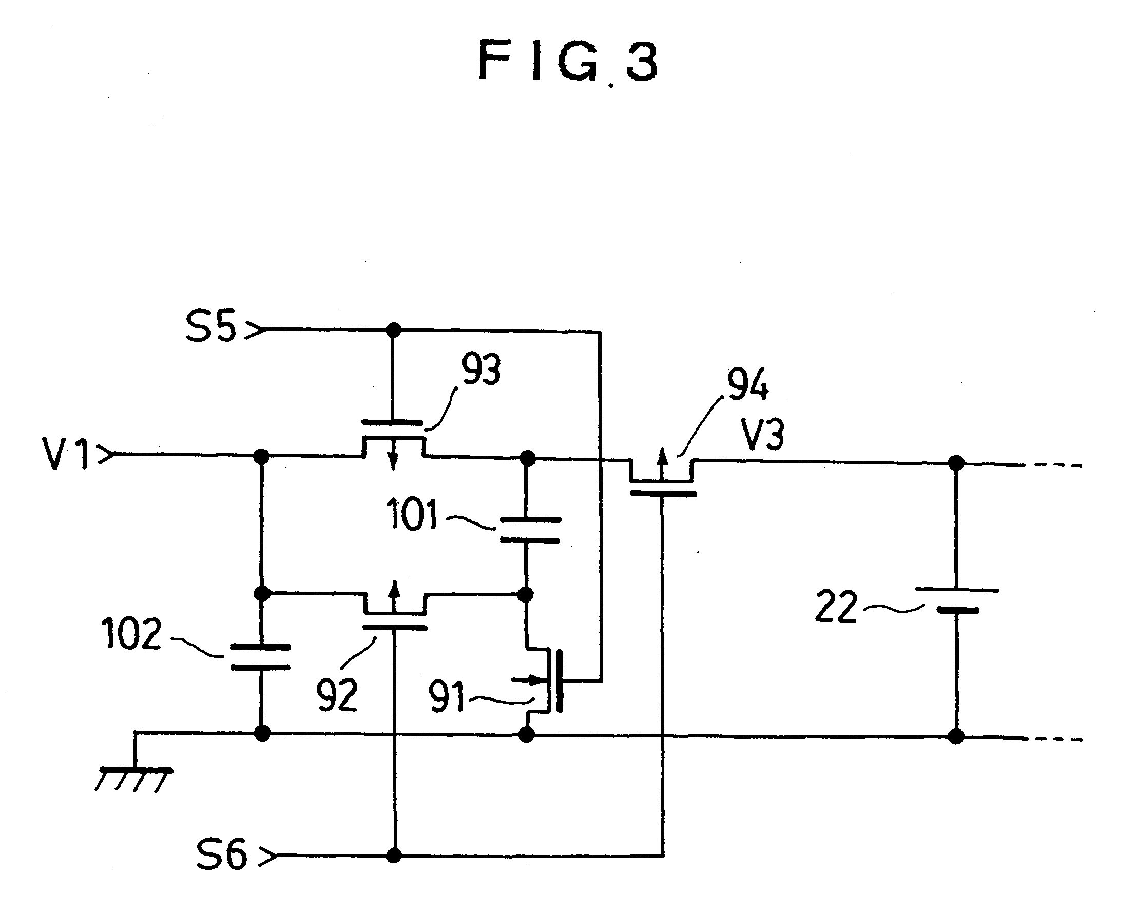
FIG. 1 is a block circuit diagram showing a system configuration of an electronic timepiece which is an embodiment of the thermoelectric system according to the present invention. FIG. 2 is a circuit diagram showing a detail circuit configuration of a controller in the electric timepiece, and FIG. 3 is a circuit diagram showing a detail circuit configuration of the voltage-up converter. FIG. 4 is a sectional view showing an outline of the inner structure when the electronic timepiece is a wrist watch, and FIG. 5 is a waveform diagram of voltages and signals in FIG. 1 to FIG. 3 to explain the operation of the electronic timepiece.

Explanation of the System Configuration: FIG. 1

First, a system configuration of the electronic timepiece which is an embodiment of the thermoelectric system according to the present invention will be explained with re...


PUM


Abstract

In order to optimally control supply of electric power to a load means and efficiently utilize generated energy of a thermoelectric power generator in consideration of influence of the Peltier effect against generated voltage of the thermoelectric power generator, a thermoelectric system is structured by connecting a load means (20) utilizing the generated power of the thermoelectric power generator (10), and a controller (30) for measuring the generated voltage (V1) of the thermoelectric power generator (10) and controlling power supply and suspension of the power supply to the load means (20) in accordance with the measured result to the thermoelectric power generator (10) provided with a plurality of thermocouples electrically in series, and a compensating means to perform measurement with compensating for the generated voltage when power is supplied from the thermoelectric power generator (10) to the load means (20) continuously for more than a predetermined period of time, is provided to the controller.

Description

BACKGROUND OF THE INVENTION1. Field of the InventionThe present invention relates to a thermoelectric system to supply power (electric energy) generated by a thermoelectric power generator which generates electricity by utilizing an outside temperature difference to a load so as to operate the load. The present invention especially relates to a thermoelectric system which provides a function to adequately control power supply from a thermoelectric power generator to a load, compensating for an influence of the Peltier effect peculiar to the thermoelectric power generator.2. Description of the Related ArtThere exists a thermoelectric system which generates electric power from heat energy caused by an outside temperature difference using a thermocouple and drives electronic equipment such as an electronic timepiece and the like utilizing electric energy obtained from the power generation.An electronic timepiece driven by generated power from a thermoelectric power generator shown in F...

Claims


Application Information

Patent Timeline
IPC IPC(8): G04C10/00G04G19/00G04G19/04
CPCG04C10/00G04G19/04
Inventor NAGATA, YOICHI
Owner CITIZEN WATCH CO LTD
Learn More