Power converter having a low voltage regulator powered from a high voltage source

a technology of low voltage regulator and power converter, which is applied in the direction of electric variable regulation, process and machine control, instruments, etc., can solve the problems of increasing the cost and size of the transformer t1

Inactive Publication Date: 2001-05-15
MICROSEMI
View PDF10 Cites 51 Cited by
  • Summary
  • Abstract
  • Description
  • Claims
  • Application Information

AI Technical Summary

Benefits of technology

A power supply arrangement and related method are disclosed. A transformer is provided having a first terminal of a primary winding connected to a power source. A switching element, such as a transistor, is coupled between a second terminal of the primary winding and a power source common, and operates to switch the power source output. A power supply is provided, which in a preferred embodiment, operates to power control circuitry which controls the state of the switching element.

Problems solved by technology

Thus, the cost and size of transformer T1 are increased.

Method used


Image

  • Power converter having a low voltage regulator powered from a high voltage source
  • Power converter having a low voltage regulator powered from a high voltage source
  • Power converter having a low voltage regulator powered from a high voltage source

Examples


Embodiment Construction

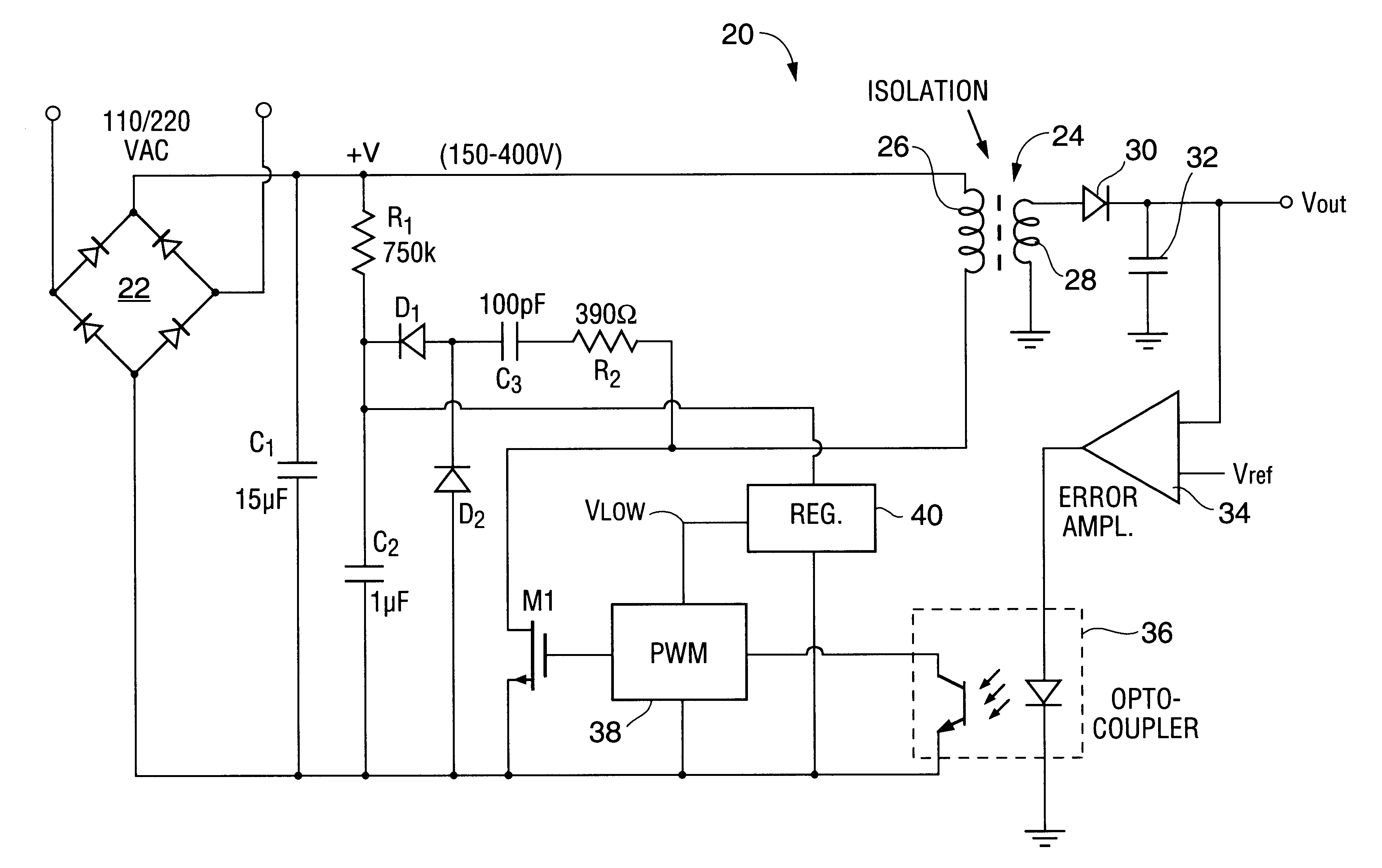
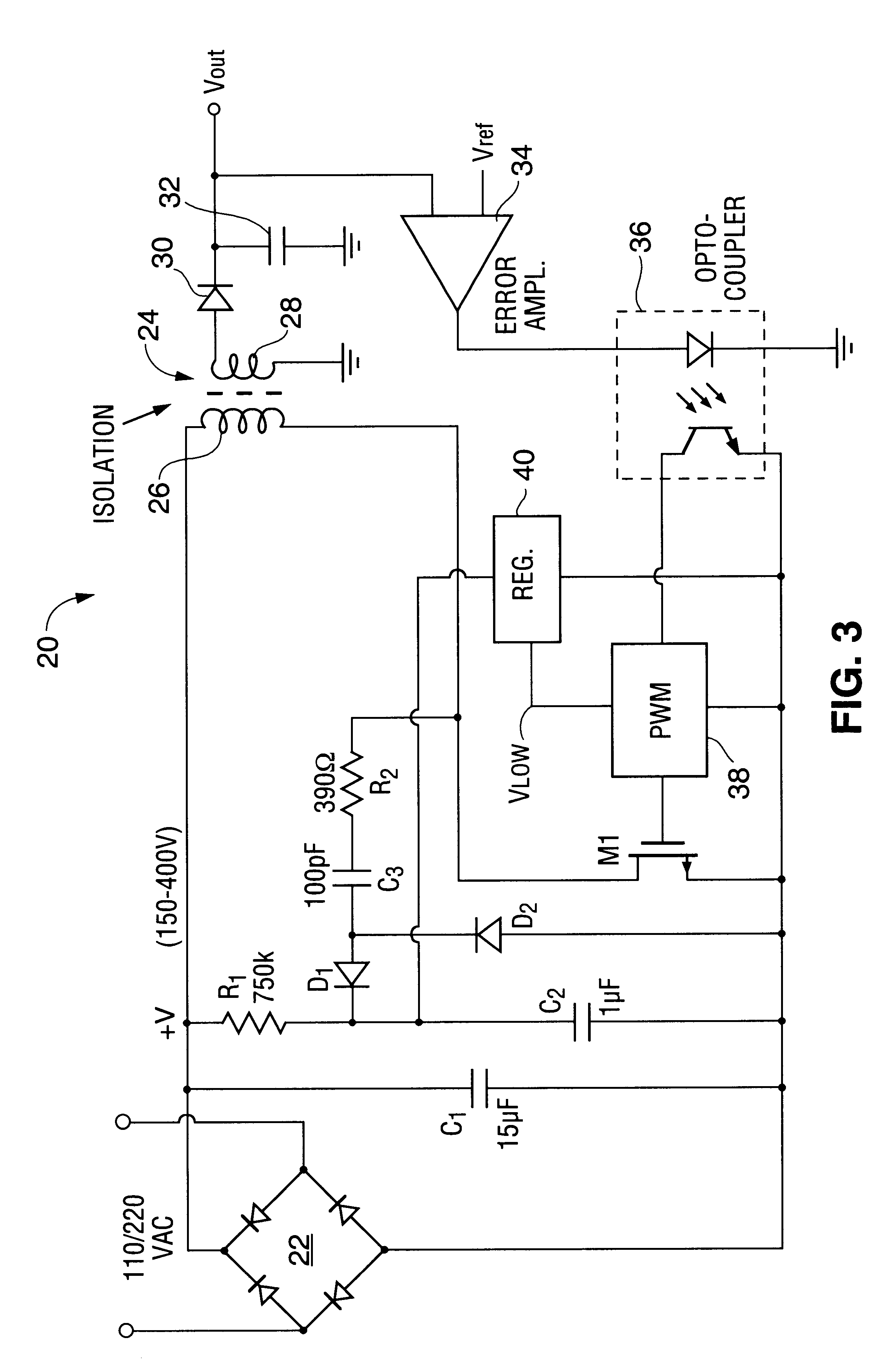
Referring again to the drawings, FIG. 3 is a switching voltage regulator circuit 20 which incorporates one embodiment of the present invention. The regulator circuit 20 is powered from a 110 / 220 V AC source which is rectified by a full wave rectifier 22. The output of rectifier 22 is filtered to some extent by capacitor Cl so that the output +V is a large and poorly regulated DC voltage having a large 50 Hz or 60 Hz ripple component.

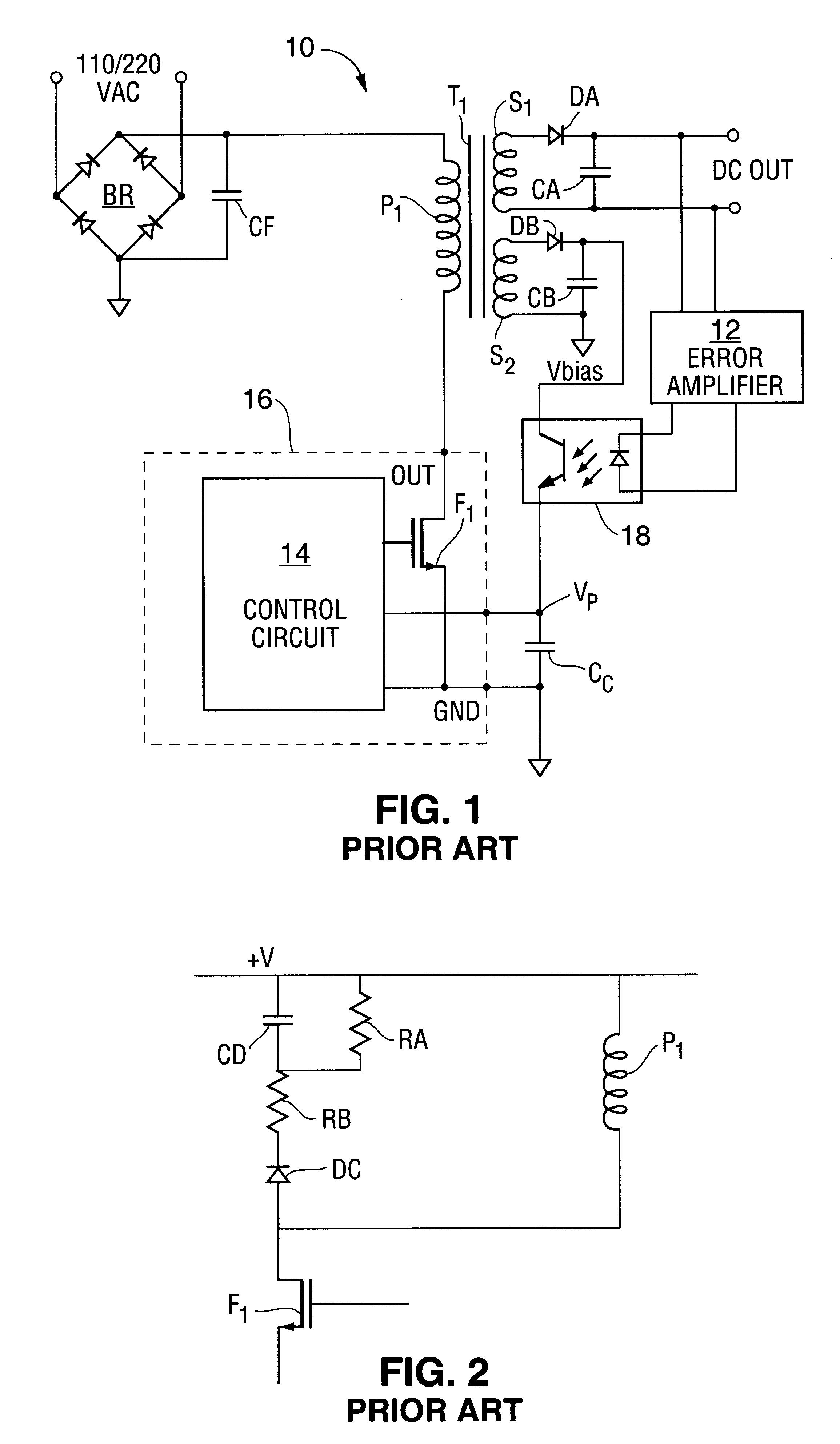
The positive side of the rectifier output is connected to one terminal of the primary winding 26 of a transformer 24. The negative side of the rectifier output is connected to a node sometimes referred to as the power source common. Further, the second terminal of primary winding 26 is connected to the drain of a high voltage FET M1. FET M1 operates to chop the DC voltage in a manner similar to that previously described in connection with FIG. 1.

A secondary winding 28 of transformer 24 is connected to a rectifier circuit including diode 30 and to a filte...


PUM


Abstract

A power supply arrangement including a transformer and a switching element coupled to a primary winding of the transformer and a power supply. The power supply includes a capacitor having a first terminal coupled to a junction of the primary winding and the switching element and a first diode coupled between the capacitor and an output node. The power supply further includes a discharge element, such as a resistor or a diode, coupled between the junction of the first diode and the capacitor and a power supply common. A voltage regulator, such as a Zener diode, is connected to the output node to produce a regulated voltage powered by the voltage applied to the transformer primary winding, with the regulated voltage being used to power the control circuitry.

Description

BACKGROUND OF THE INVENTION1. Field of the InventionThe present invention relates generally to power supplies and, in particular, to power supplies suitable for operating from a high voltage supply input and for powering low-voltage-rated circuitry.2. Description of the Related ArtIn many applications where high voltages must be regulated or otherwise controlled in some manner, the circuitry for controlling the high voltages must be constructed to withstand high voltages. Since components with a high break-down voltage are expensive when compared to components with lower break-down voltages, there is an advantage is using low break-down voltage components.FIG. 1 is a diagram of a conventional switching voltage regulator circuit which controls operation of a high voltage, but which uses low break-down voltage components. Further details regarding the construction and operation of the FIG. 1 circuit are disclosed in U.S. Pat. No. 5,313,381 entitled "Three-Terminal Switched Mode Power ...

Claims


Application Information

Patent Timeline
Patent Type & Authority Patents(United States)
IPC IPC(8): H02M3/335H02M3/24
CPCH02M3/335H02M2001/0006H02M1/0006
Inventor IRISSOU, PIERRE R.CAMENZIND, HANS R.
Owner MICROSEMI
Why Eureka
Try Eureka