Writing implement

a technology of implements and flanges, which is applied in the direction of nib removers, printing, ink reservoir pens, etc., can solve the problems of large force, damage to the flange portion of the pen point hold body, and the end portion of the shaft barrel, so as to achieve the effect of preventing damage to the flange portion of the pen point hold body, and preventing damage to the flange portion of the tail plug

Inactive Publication Date: 2001-06-12
THE PILOT INK CO LTD
View PDF6 Cites 5 Cited by
  • Summary
  • Abstract
  • Description
  • Claims
  • Application Information

AI Technical Summary

Problems solved by technology

However, in the above-mentioned conventional writing implements, since the groove for forcible opening is shallow inwardly in a diameter direction thereof, when forcing open the tail plug or pen point hold body, the coin or tool can be inserted into the groove only in a small amount.
Namely, the tail plug or pen point hold body cannot be forced open easily; or, a large force is necessary to force open the tail plug or pen point hold body.
Therefore, there is a fear that the end portion of the shaft barrel, the flange portion of the tail plug, or the flange portion of the pen point hold body can be damaged.

Method used


Image

  • Writing implement
  • Writing implement
  • Writing implement

Examples


first embodiment

(Summary of the structure of the first embodiment)

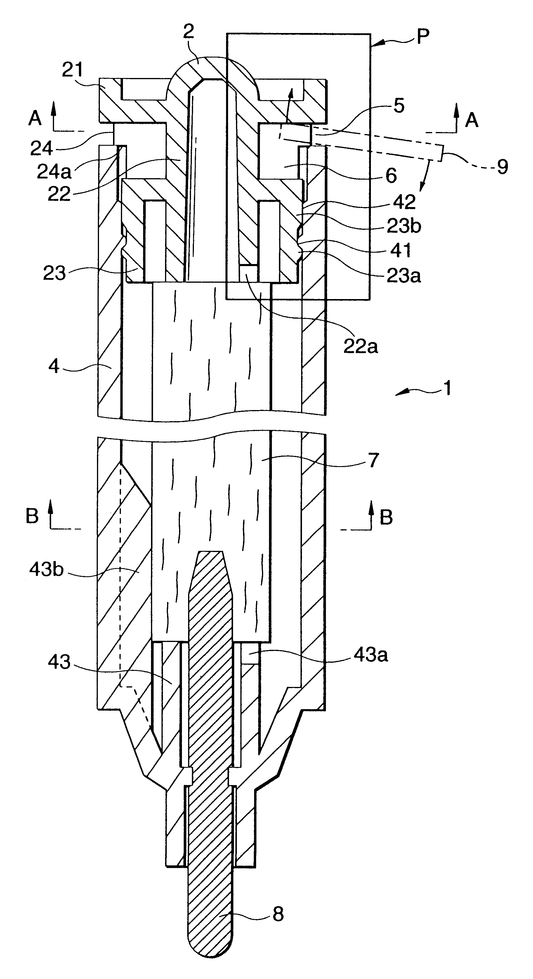
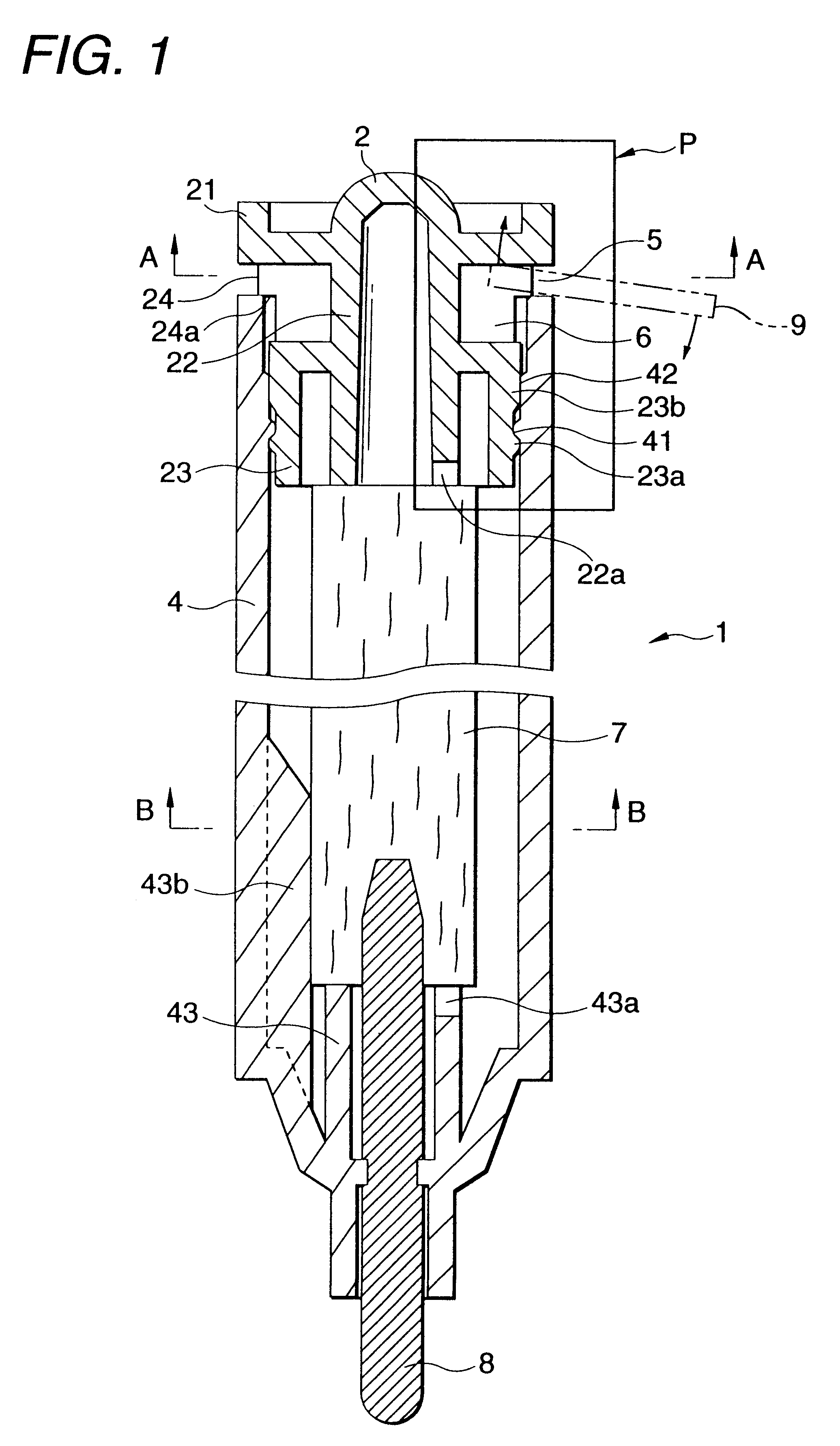
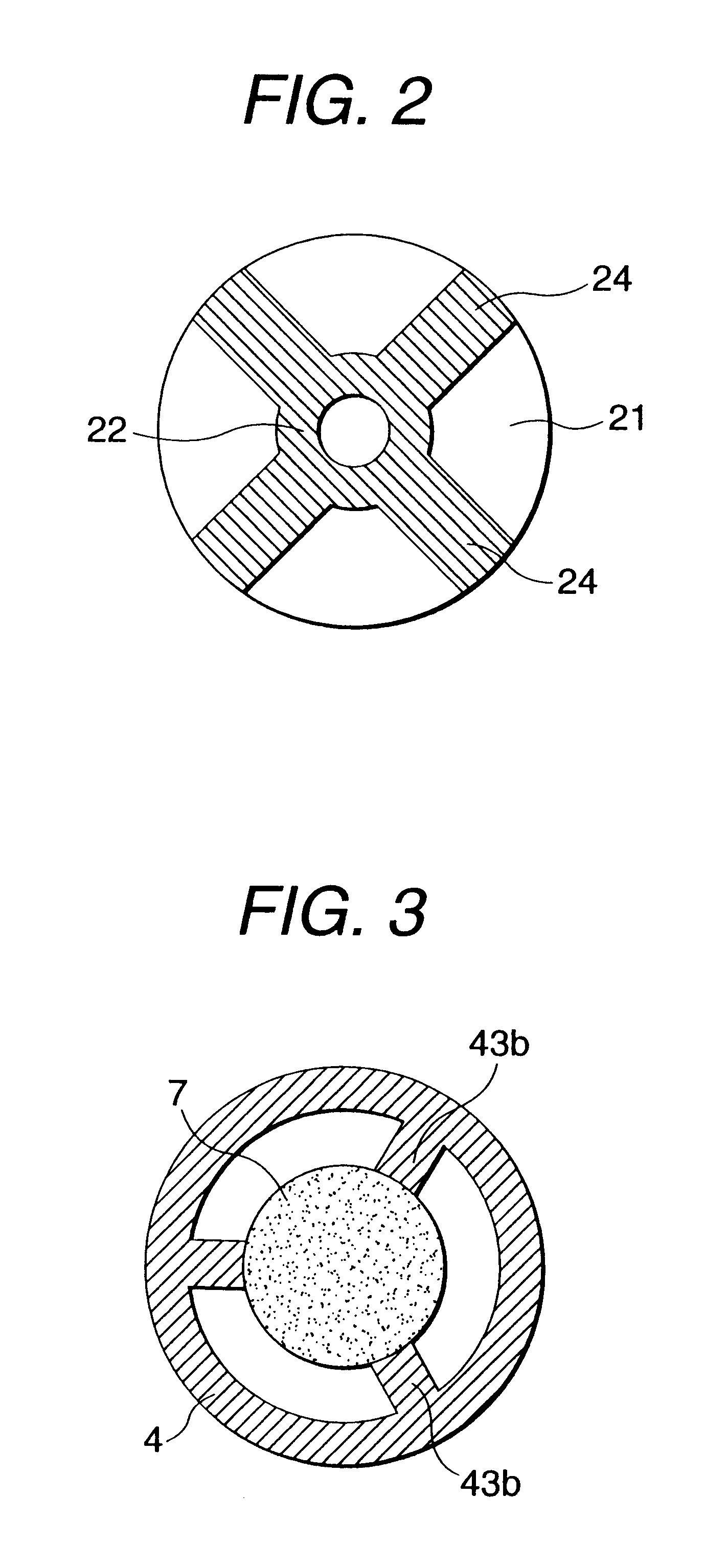
A writing implement 1 comprises a shaft barrel 4 and a tail plug 2. The shaft barrel 4 includes an ink storing body 7 stored in an interior portion thereof and a pen point 8 mounted on a front end portion thereof. The tail plug 2 is removably mounted on an opening formed at a rear end (hereinafter referred to "rear end opening") of the shaft barrel 4.

(Shaft barrel)

The shaft barrel 4 can be formed of synthetic resin (for example, polypropylene) by injection molding. The front end portion of the shaft barrel 4 is reduced in diameter in a tapered manner, while the pen point 8 is held in the tapered front end portion of the shaft barrel 4. Also, the shaft barrel 4 has a tubular portion 43 which is provided on an inner surface of the front end portion of the shaft barrel 4 and encloses the outer periphery of the pen point 8. The tubular portion 43 is formed integral with the inner surface of the shaft barrel 4 and projects therefrom in th...

second embodiment

Now, description will be given below of a second embodiment of a writing implement according to the invention. (see FIGS. 7 and 8).

(Summary of the structure of the second embodiment)

A writing implement 1 comprises a shaft barrel 4 (which, similarly to the first embodiment, is an injection-molded body of synthetic resin) and another plug body in the form of a pen point hold body 3. The shaft barrel 4 stores an ink storing body 7 (which, similarly to the first embodiment, is a worked body of synthetic resin fibers) in the interior portion thereof. The pen point hold body 3 is removably mounted on an opening formed at the front end (hereinafter referred to "front end opening") of the shaft barrel 4 and includes a pen point 8 (which, similarly to the first embodiment, is a bar-shaped resin worked body of synthetic resin).

(Pen point hold body)

The pen point hold body 3 can be formed of synthetic resin (for example, polypropylene) by injection molding. The pen point hold body 3 comprises a...


PUM


Abstract

The writing implement 1 comprises a shaft barrel 4 and a tail plug 2. The shaft barrel 4 includes an ink storing body 7 stored in an interior portion thereof and a pen point 8 mounted on a front end portion thereof. The tail plug 2 is removably mounted on an opening formed at the rear end of the shaft barrel 4. The tail plug 2 includes a flange portion 21 which is provided backwardly of the rear end portion of the shaft barrel 4. Between the front surface of the flange portion 21 and the rear end portion of the shaft barrel 4, there is formed a groove 5 for forcibly opening. The groove 5 is formed more deeply inwardly in the diameter direction of the shaft barrel 4 than the inner surface of the rear end opening of the shaft barrel 4.

Description

1. Field of the InventionThe present invention relates to a writing implement. In detail, the invention relates to a writing implement which comprises a shaft barrel storing ink in an interior portion thereof and a plug body (for example, a tail plug or a pen point hold body) removably mounted on one end of the shaft barrel. In the present invention, a term "front" means the pen point side of the writing implement, whereas a term "rear" means the tail plug side thereof. Also, an expression "front surface" means the axial-direction outer surface of the writing implement, whereas an expression "back surface" means the axial-direction inner surface thereof.2. Description of the Related ArtConventionally, for example, in Japanese Patent Unexamined Publication No. Hei. 11-48679, there is disclosed a writing implement in which, for the purpose of removing an ink storing body stored into an interior portion of a shaft barrel, a tail plug is removably mounted on an opening formed in a rear ...

Claims


Application Information

Patent Timeline
Patent Type & Authority Patents(United States)
IPC IPC(8): B43K13/00B43K11/00B43K3/00B43K8/00B43K8/02
CPCB43K11/005B43K13/005B43K8/00
Inventor OIKE, SHIGERU
Owner THE PILOT INK CO LTD
Why Eureka
Try Eureka