Liquid crystal compositions

a technology of liquid crystal composition and composition, applied in the direction of liquid crystal composition, chemical apparatus and processes, etc., can solve the problems of tn liquid crystal elements having a long (slow) electrooptic response time of several tens milliseconds, display devices using tn liquid crystal elements hardly following animation of quick motion, and changing the color tone of the imag

Inactive Publication Date: 2001-06-12
MITSUI CHEM INC
View PDF10 Cites 24 Cited by
  • Summary
  • Abstract
  • Description
  • Claims
  • Application Information

AI Technical Summary

Benefits of technology

The liquid crystal composition of the invention has an applied voltage-light transmittance relationship shown by a V-shaped hysteresis curve, which is suitable for performing voltage gradation display by an active element driving system such as a TFT driving system. The liquid crystal composition having such an appl...

Problems solved by technology

The TN liquid crystal elements, however, have a long (slow) electrooptic response time of several tens milliseconds.
Therefore, the display devices using the TN liquid crystal elements hardly follow animation of quick motions, even when the display devices are driven by the use of active elements.
Further, the angle of field of an image displayed by the use of the TN liquid crystal element is narrow, and therefore when the image displayed by the use of the TN liquid crystal element is observed with an angle beyond the fixed angle of fi...

Method used


Image

  • Liquid crystal compositions
  • Liquid crystal compositions
  • Liquid crystal compositions

Examples


example 1

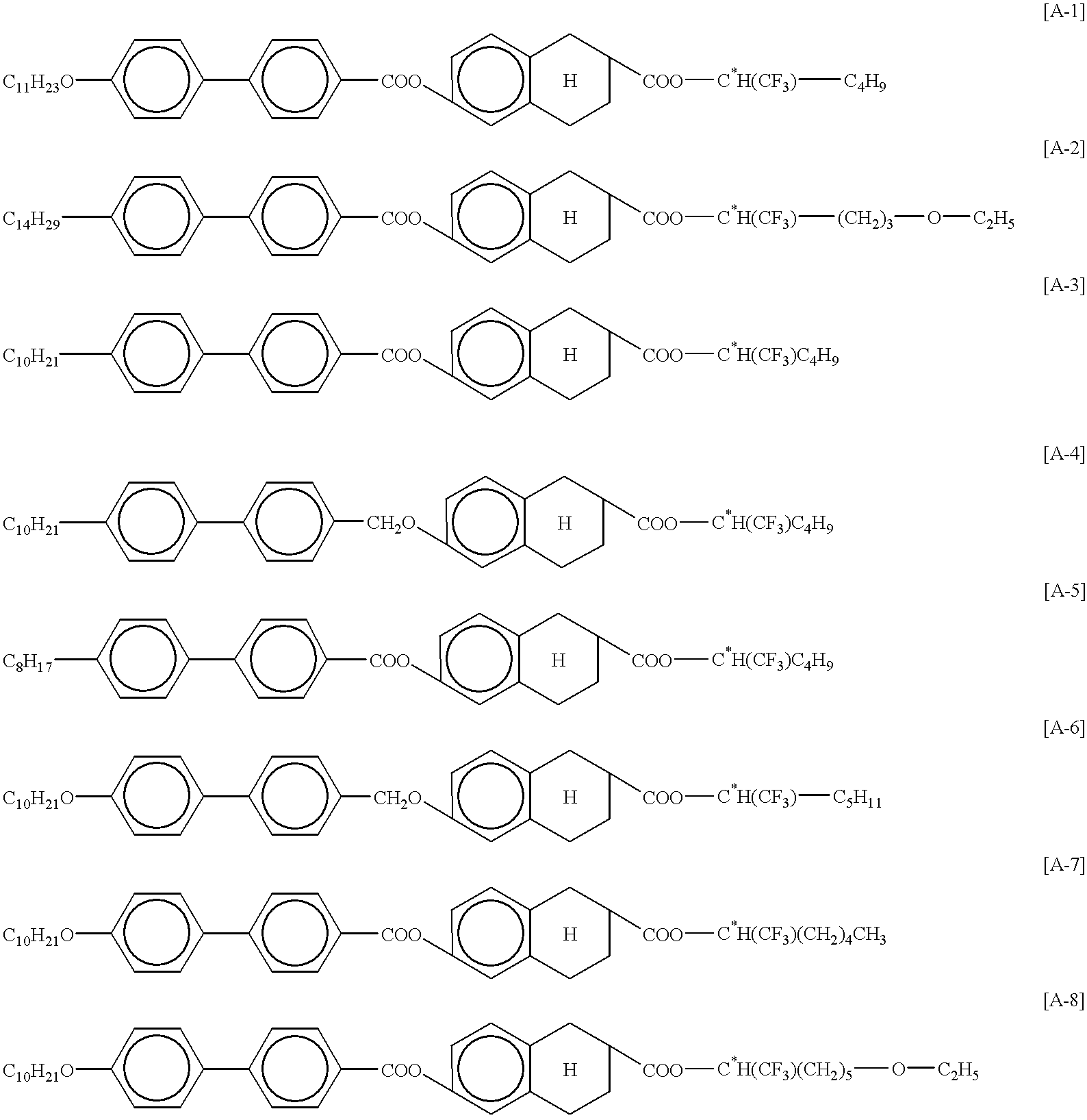
The following antiferroelectric liquid crystal compound 1 and the following antiferroelectric liquid crystal compound 2 were mixed in a mixing ratio shown in the following table to prepare a liquid crystal composition 1. The liquid crystal composition 1 was injected into the liquid crystal cell having the above structure, and the injection opening was sealed with an epoxy adhesive.

Then, a rectangular wave of .+-.15 V and 60 Hz was applied between the transparent electrodes of the liquid crystal cell. Thereafter, the voltage was temporarily set at 0 V, and the cell was arranged between a polarizer and a analyzer in the crossed Nicols state in such a manner that the optic axis of the liquid crystal cell under application of no voltage would agree with the absorption axis of the polarizer. The surrounding temperature of the cell was set at 30.degree. C. Then, a triangular wave of .+-.15 V and 100 mHz was applied between the transparent electrodes to measure a transmitted light intensit...

example 2

The following ferroelectric liquid crystal compound 3 and the following liquid crystal compound 4 capable of being in neither antiferroelectric phase nor ferroelectric phase were mixed in a mixing ratio shown in the following table to prepare a liquid crystal composition 2. The liquid crystal composition 2 was subjected to the same measurement as in Example 1.

As a result, a V-shaped hysteresis curve showing an applied voltage-light transmittance relationship was obtained, similarly to Example 1. The light transmittance (transmitted light quantity) I.sub.32 of the liquid crystal composition at the applied voltage V.sub.32 of 2.5 V was 0.23. The cell was observed by a polarizing microscope with applying a voltage. As a result, it was confirmed that, by the application of voltage, the optic axes were uniformly changed, similarly to Example 1.

example 3

The following ferroelectric liquid crystal compound 5 and the following ferroelectric liquid crystal compound 6 were mixed in a mixing ratio shown in the following table to prepare a liquid crystal composition 3. The liquid crystal composition 3 was subjected to the same measurement as in Example 1.

As a result, a V-shaped hysteresis curve showing an applied voltage-light transmittance relationship was obtained, similarly to Example 1. The light transmittance (transmitted light quantity) I.sub.32 of the liquid crystal composition at the applied voltage V.sub.32 of 2.1 V was 0.18. The cell was observed by a polarizing microscope with applying a voltage. As a result, it was confirmed that, by the application of voltage, the optic axes were uniformly changed, similarly to Example 1.


PUM


Abstract

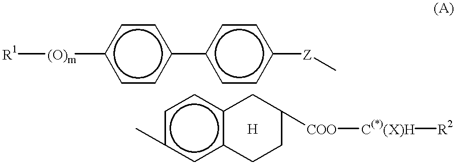
The liquid crystal composition of the invention contains at least two compounds represented by the following formula (A) and each having different structures, one or more methylene group in the alkylene group R1 may be substituted with -O- groups, not less than 50% by weight, and has a transmitted light quantity I32 satisfying the condition of 0.5<=I32<=0.50,wherein R1 is an alkyl group of 2 to 20 carbon atoms; m is 0 or 1; Z is a -COO- group or a -CH2O- group; X is a hydrogen atom, a methyl group or a trifluoromethyl group; and R2 is a group selected from the group consisting of a straight-chain alkyl group of 1 to 5 carbon atoms, an ether group represented by -(CH2)p-O-(CH2)qCH3 and an alkene group wherein a terminal ethyl group consisting a straight-chain alkyl group of 2 to 5 carbon atoms is replaced with a group having a C=C double bond.

Description

The present invention relates to liquid crystal compositions, and particularly to smectic liquid crystal compositions favorably used for an active element driving system. More particularly, the invention relates to "threshold value-free antiferroelectric liquid crystal compositions".Attempts to use liquid crystal elements utilizing electrooptic effect of twisted nematic (TN) liquid crystals (referred to as "TN liquid crystal elements" hereinafter) as display elements of animation display devices have been heretofore made.The TN liquid crystal elements, however, have a long (slow) electrooptic response time of several tens milliseconds. Therefore, the display devices using the TN liquid crystal elements hardly follow animation of quick motions, even when the display devices are driven by the use of active elements. Further, the angle of field of an image displayed by the use of the TN liquid crystal element is narrow, and therefore when the image displayed by the use of the TN liquid...

Claims


Application Information

Patent Timeline
IPC IPC(8): C09K19/02C09K19/32
CPCC09K19/0266C09K19/322C09K19/2007C09K2019/2042
Inventor SAKAI, YUKARINISHIYAMA, SHINICHIMARUYAMA, TOYOTAROFUJIYAMA, TAKAHIRO
Owner MITSUI CHEM INC
Why Eureka
Try Eureka