Pipette with improved pipette tip and mounting shaft combination

a technology of mounting shaft and pipette, which is applied in the direction of sampling, laboratory glassware, instruments, etc., can solve the problems of unfavorable increase in the axial force required to mount, and achieve the effect of uniform tip interferen

Inactive Publication Date: 2001-06-19
RAININ INSTR
View PDF2 Cites 71 Cited by
  • Summary
  • Abstract
  • Description
  • Claims
  • Application Information

AI Technical Summary

Benefits of technology

The present invention incorporates in an air displacement pipette the concept of similar frusto-conical distal and proximal end portions on a pipette tip mounting shaft and pipette tip respectively. The frusto-conical distal and proximal end portions have substantially parallel inwardly and downwardly tapering surfaces incorporating axially spaced annular sealing and lateral support zones and regions on the mounting shaft and tip, respectively. Further, the present invention incorporates cooperative means on the shaft and tip for insuring uniform depth of mounting shaft penetration into the pipette tip to maintain uniform tip interference with the mounting shaft as successive tips are mounted on and ejected from the mounting shaft.
In particular, the present invention comprises a combination of a pipette tip mounting shaft and pipette tip in an air displacement pipette. The mounting shaft comprises an axially elongated body including a frusto-conical distal end portion having an axially tapering outer surface with annular axially spaced outer surface regions defining an annular sealing zone and an axially tapering annular lateral support zone. The pipette tip is an elongated tube comprising an open frusto-conical proximal end portion, an open conical distal end and annular axially spaced inner surface regions on the axially tapering frusto-conical inner surface of the proximal end portion defining an annular sealing region and an axially tapering annular lateral support region. The axial tapering of the mounting shaft and pipette tip are one and one-half degrees or more from the longitudinal axis of the shaft and preferably between one and one-half and five or six degrees. The outer diameter of the annular sealing zone on the mounting shaft is slightly greater than the inner diameter of the annular sealing region on the pipette tip and the sidewall of the tip in the area of the annular sealing region is sufficiently thin that the annular sealing region expands slightly to form an interference fit and air tight seal between the mounting shaft and the pipette tip when the sealing zone penetrates the sealing region. The axial spacing of the sealing and support zones is substantially equal to the axial spacing of the sealing and support regions. Also, the outer diameters of the mounting shaft in the axially tapering lateral support zone are slightly less than or substantially equal to corresponding inner diameters of the proximal end portion of the tip in at least some circumferential portions of the axially tapering lateral support region. This allows for some minimal contact between the support zone and region without creating a secondary air tight seal which would result in an undesired increase in the axial forces required to mount and eject the pipette on and from the shaft. With such a structural configuration, as the sealing zone penetrates the sealing region, the support region receives the support zone and provides lateral support therefor which prevents transverse rocking of the pipette tip on the mounting shaft as might otherwise occur during touching off of the pipette tip and an accompanying undesired dislodging of the tip from the shaft.
Still further, for pipette tip and shaft combinations wherein the interference fit between the sealing zone and region is about 0.075 mm to about 0.2 mm and the wall thickness of the pipette tip in the sealing region is between 0.2 and 0.5 mm, it has been discovered that the desired minimal tip mounting and ejection forces associated with the present invention still may be achieved and the lateral stability of the tip on the shaft further enhanced when there is a small interference fit between the support region and zone. The small interference is provided by the lateral support region of the tip having an inner diameter which is slightly less than the outer diameter of the lateral support zone of the shaft, eg. less than 0.075 mm. Further, when the shaft and tip are concentric and substantially circular in the support zone and region, a secondary air tight seal may be created between the support zone and region without creating an undesired increase in the axial forces required to mount and eject the tip on and from the shaft.

Problems solved by technology

This allows for some minimal contact between the support zone and region without creating a secondary air tight seal which would result in an undesired increase in the axial forces required to mount and eject the pipette on and from the shaft.

Method used


Image

  • Pipette with improved pipette tip and mounting shaft combination
  • Pipette with improved pipette tip and mounting shaft combination
  • Pipette with improved pipette tip and mounting shaft combination

Examples


Embodiment Construction

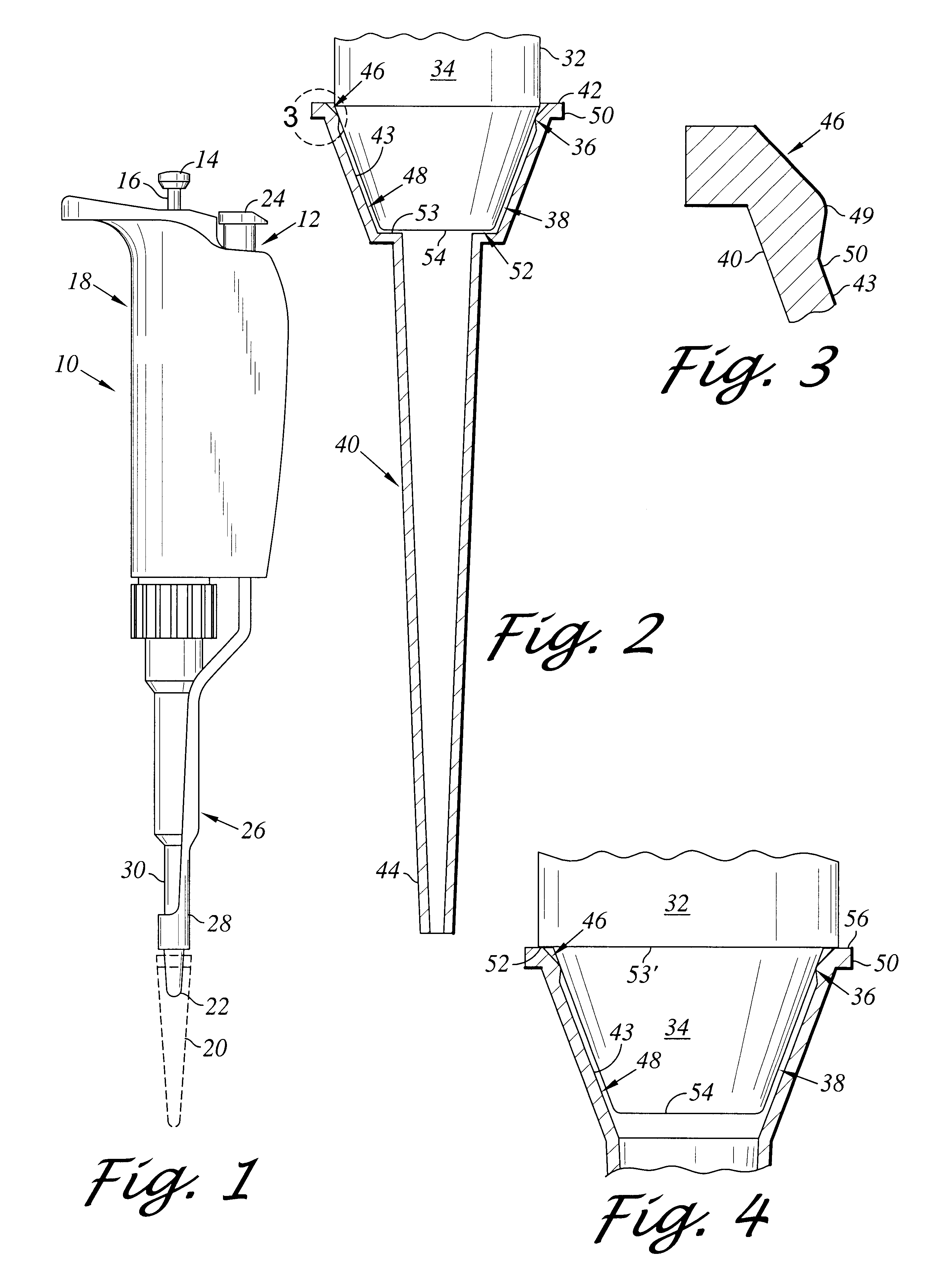
FIG. 1 illustrates a standard manual pipette resembling the PIPETMAN pipette sold exclusively in the United States by the Rainin Instrument Co. Inc., assignee of the present invention. The manual pipette is designated in FIG. 1 by the number 10 and includes a pipette tip ejector mechanism 12 described in U.S. Pat. No. 3,991,617 issued Nov. 16, 1976, which is incorporated herein by this reference.

The pipette 10 comprises a push button 14 connected by a rod 16 to a piston (not shown) located in the body or housing 18 of the pipette. The push button 14 may be depressed by a user exerting a downward force on the push button to cause downward movement of the piston of the pipette. When the push button 14 is released, a quantity of liquid to be sampled is sucked into a disposable pipette tip 20 releasably secured to a lower end of a pipette tip mounting shaft 22 of the pipette. The sample then may be transferred into another vessel by once more exerting a downward force on the push button...


PUM


Abstract

An air displacement pipette having axially spaced annular sealing and frusto-conical lateral support zones and regions on the pipette's mounting shaft and tip, respectively, in combination with structure for insuring uniform depth of mounting shaft penetration into the pipette tip to maintain uniform tip interference with the mounting shaft as successive tips are mounted on and ejected from the mounting shaft whereby the pipette tip is easily and firmly mountable on and ejectable from the pipette tip mounting shaft by the application of reduced user generated axial forces.

Description

The present invention relates to improvements in pipettes and, more particularly, to air displacement pipettes including a unique pipette tip tailored to the distal end of the pipette's tip mounting shaft such that the tip is easily insertable by a pipette user onto the mounting shaft to a fluid tight position in which the tip is secured against undesired lateral rocking on or displacement from the shaft and, after use, is easily ejectable from the shaft by the pipette user.BACKGROUND OF INVENTIONDuring the development of the unique pipette tip described in U.S. patent application Ser. No. 09 / 188,030, filed Nov. 6, 1998 now U.S. Pat. No. 6,197,259 and entitled "Easy Eject Pipette Tip" and the development of the novel pipette tip and tip mounting shaft combination described in U.S. patent application Ser. No. 09 / 188,031, filed Nov. 6, 1998 now U.S. Pat. No. 6,168,761 and entitled "Pipette With Improved Pipette Tip and Mounting Shaft", both applications being incorporated herein by th...

Claims


Application Information

Patent Timeline
Patent Type & Authority Patents(United States)
IPC IPC(8): B01L3/02
CPCB01L3/0279B01L3/02
Inventor PETREK, JAMES S.
Owner RAININ INSTR
Why Eureka
Try Eureka