Airplane with combined-wing layout of flying wing and forward-swept wings

A forward swept wing and flying wing technology, applied in the field of new aircraft, can solve the problems of aerodynamic divergence and poor aerodynamic effect of the forward swept wing, and achieve the effects of better landing gear arrangement, improved static stability, and better aerodynamic lift.

Active Publication Date: 2014-02-05
BEIHANG UNIV
View PDF4 Cites 26 Cited by
  • Summary
  • Abstract
  • Description
  • Claims
  • Application Information

AI Technical Summary

Problems solved by technology

[0003] In order to overcome the problems of poor aerodynamic effect and forward-swept wing aerodynamic divergence of existing flying-wing layout aircraft, and to pursue a better lift-to-drag ratio, the present invention provides a flying-wing and forward-sweeping wing joint-wing layout aircraft

Method used


Image

  • Airplane with combined-wing layout of flying wing and forward-swept wings
  • Airplane with combined-wing layout of flying wing and forward-swept wings
  • Airplane with combined-wing layout of flying wing and forward-swept wings

Examples


Embodiment Construction

[0012] The present invention will be further described in detail below in conjunction with the accompanying drawings and embodiments.

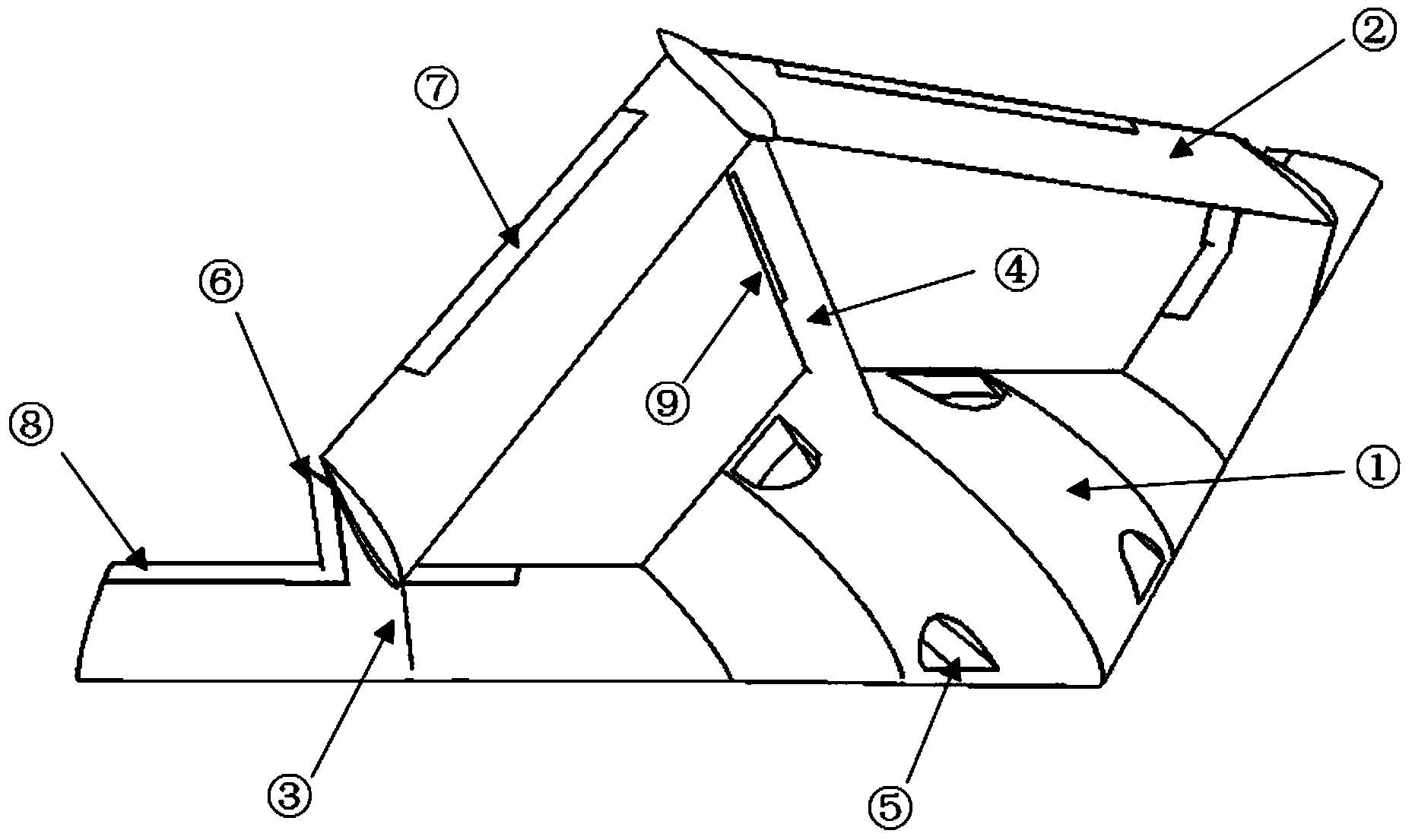
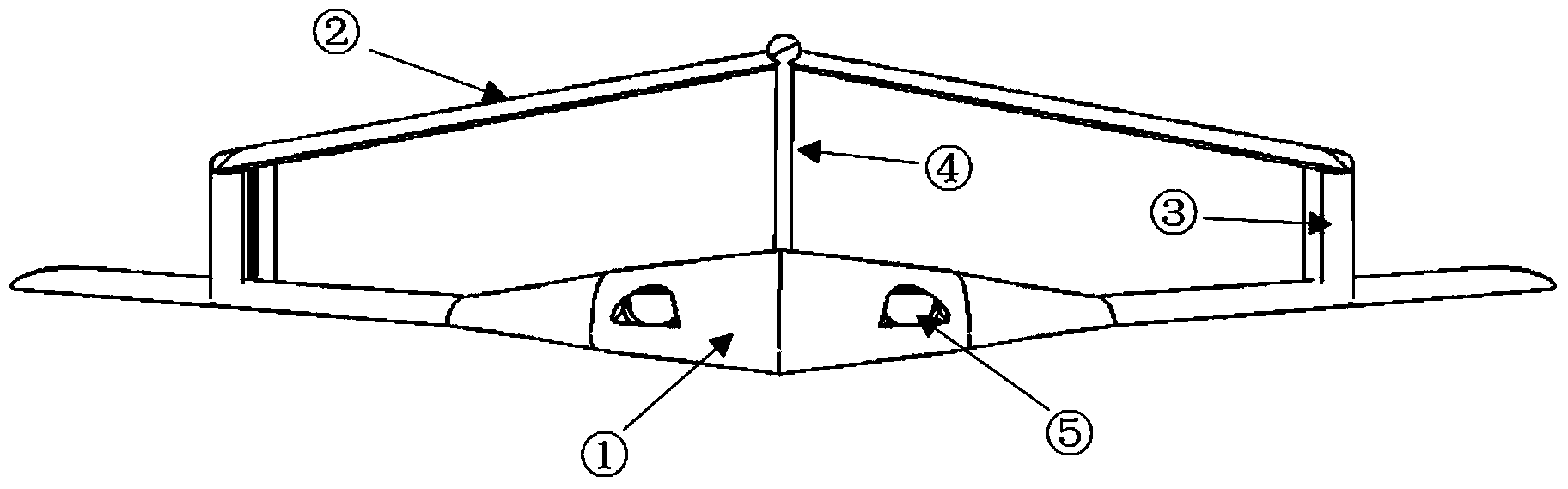
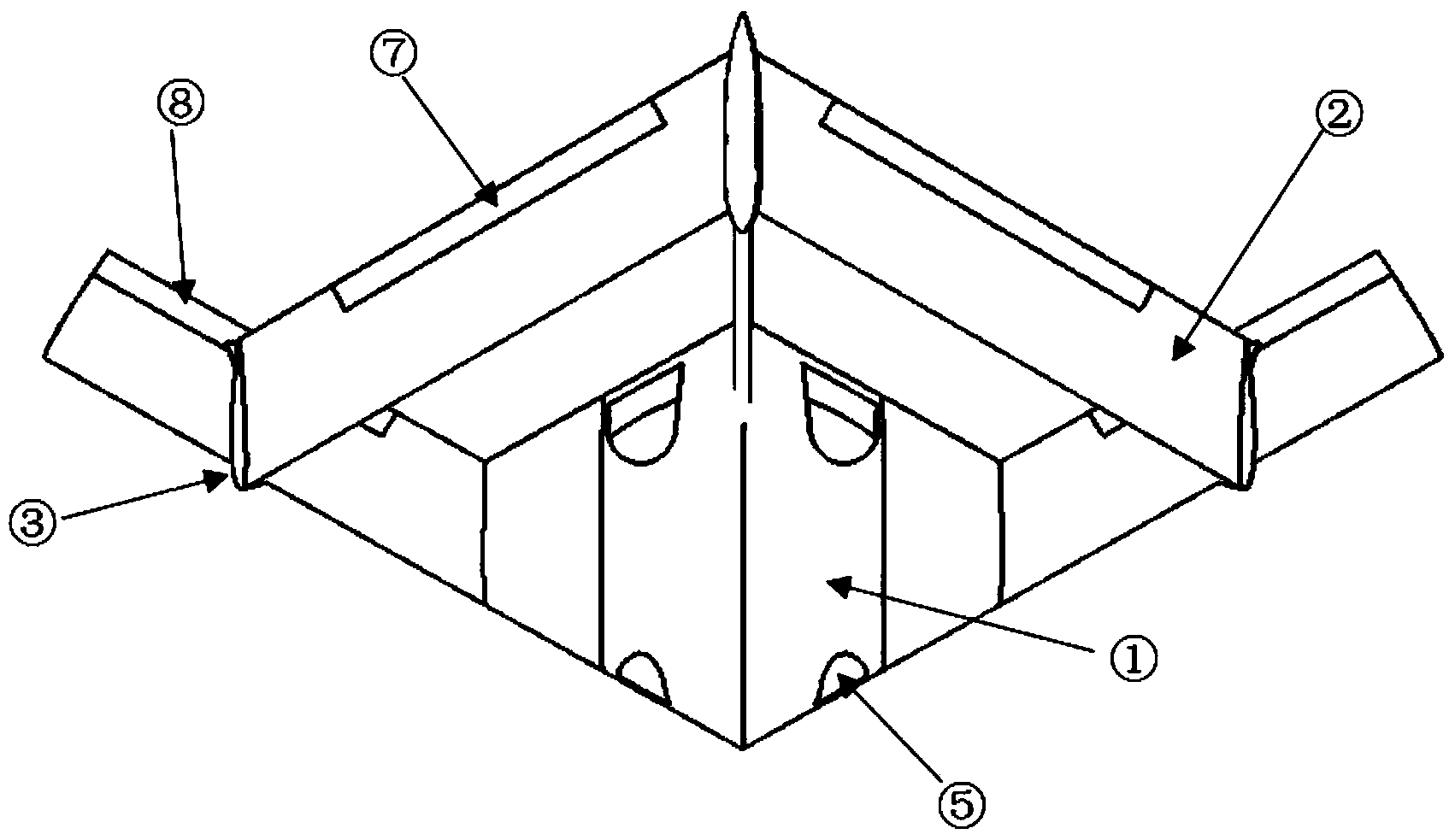
[0013] Such as figure 1 , Figure 2-a , Figure 2-b and Figure 2-c Shown is an implementation example of the flying wing and forward-swept wing joint-wing layout aircraft provided by the present invention. The flying-wing and forward-swept-wing joint-wing layout aircraft of the present invention is improved on the swept-wing flying-wing ① fuselage, and the left and right connecting wing columns ③ are added at 70% of the wingspan outside the wings on both sides, and the aircraft tail is added. The tail column ④, the left and right connecting wing columns ③ and the tail column ④ are thin airfoil columns, and the horizontal upper wing ② is fixed on the top of the three columns, and the upper wing ② is a forward-swept wing placed horizontally, thus forming a rear The layout form of swept wing flying wing and forward swept wing joint wing. Th...


PUM


Abstract

The invention provides an airplane with a combined-wing layout of a flying wing and forward-swept wings. The airplane is characterized in that thin-wing type vertical columns A and B are additionally arranged at the 70% wingspan positions of the outer sides of two side wings of a flying-wing airplane with backward-swept wings, a thin-wing type vertical column C is additionally arranged at the tail part of the flying-wing airplane, and horizontal forward-swept wings are additionally arranged at the top ends of the three thin-wing type vertical columns A, B and C so as to form the combined-wing layout of the flying wing and the forward-swept wings; elevators are arranged on the horizontal forward-swept wings and a rudder is arranged on the vertical column C; a duct type air inlet channel is adopted on the upper wing surface of the flying wing, and cracking type drag rudders are distributed at the thin-wing type vertical columns A and B. The airplane provided by the invention has the advantages that under the condition that the structure strength is effectively guaranteed, the effective aspect ratio of the wings is increased, the induced drag is reduced, the lift-drag characteristics of the airplane are improved, the stealth performance of the airplane is improved, direct-force control of the airplane in the vertical direction is realized and the detecting accuracy under the maneuvering condition is improved.

Description

technical field [0001] The invention belongs to the field of a novel aircraft involving a novel shape design and aerodynamic characteristics, in particular a novel aircraft layout utilizing a combination of a flying wing layout and a forward-swept wing. Background technique [0002] At present, most commercial aircraft have a conventional single-wing cylindrical fuselage layout. The military is trying and has successfully used the flying wing layout to form a good stealth effect. However, the traditional flying wing uses a swept wing, and its stall first occurs at the wingtip. , causing the center of lift to move forward and the nose to rise, further deepening the stall. The aerodynamic lift effect of the aircraft with flying wing layout is not good during flight, which greatly restricts its maneuverability and flight speed during flight, which is not conducive to high-altitude and long-endurance flight, and fuel waste occurs. However, the current forward-swept wing aircraf...

Claims


Application Information

Patent Timeline
Patent Type & Authority Applications(China)
IPC IPC(8): B64C3/00B64C9/02B64C17/00
Inventor 屈秋林张宇佳卢哲刘沛清郭昊田云
Owner BEIHANG UNIV
Why Eureka
Try Eureka