LED decorative lighting structure

a decorative lighting and structure technology, applied in the direction of electric lighting, point-like light sources, lighting and heating apparatus, etc., can solve the problems of high power consumption, low resistance, high temperature, etc., and achieve excellent water tight and dust protection ability, simple layout, and minimizing production costs

Inactive Publication Date: 2008-01-10
CHAN KK
View PDF3 Cites 58 Cited by
  • Summary
  • Abstract
  • Description
  • Claims
  • Application Information

AI Technical Summary

Benefits of technology

[0009]Accordingly, it is the main object of the present invention to provide a LED decorative lighting structure in which LED conductor blades are formed by cutting down from a strip of the same metallic material so as to eliminate a complicated production line and finishing process thereby minimizing the production cost.
[0010]Another object of the present invention is to provide a LED decorative lighting structure which has a simple layout and a stable construction so as to ensure a normal performance.
[0011]One more object of the present invention is to provide a LED decorative lighting structure which has an excellent water tight and dust protection ability in compliance with IP66 international standards applicable to any environmental condition.
[0012]To achieve these and other objects described above, the LED decorative lighting structure comprises a plurality of LEDs connected in series or parallel. Each LED has two electric conductor blades which has been directly cut down from a strip of the same metallic material. Each of the two conductor blades is equipped with a terminal which further includes a holding strip and an electric conducting strip. The holding strip is for fixing the outer insulation sheath of the circuit conductor by pressing thereon; while the conducting strip is for fixing and making electric connection with the metallic stranded core elements of the circuit conductor. The holding strip and the conducting strip in one conductor blade are disposed in different height with that of adjacent one so as to avoid short circuiting by accidental contact. After burying the individual LED die properly in its position and infusing the epoxy resin thereof, and making wire connections, the plurality of LED constructed as such are arranged in series or parallel connection thereby forming a stable and durable LED decorative lighting structure of the present invention.

Problems solved by technology

It has the inherent disadvantages of considerably large size, high power consumption accompanied with a high temperature, low resistance to the weather condition if installed in outdoor, besides, it has to occupy a large spacing for putting away when not in use.
All these cause the decorative lighting formed of the miniature incandescent lamps to become an expensive and unwelcome practice.
But it should be understood that the LED does not fit for use in general lighting application by reason of lacking in brightness.
However, such a fatal drawback of LED has been gradually improved by progressing technology in the field of lighting engineering.
However, except the polarity in the circuit should be carefully identified, the LED is difficult to be fixed to the socket without the aid of specially designed LED fixture to dependably connect its conductor blade with the circuit so as to overcome the unreliable contact by touching only.
In addition, how to hermetically seal the LED lighting structure to keep out water and dust for use in outdoor to avoid possible failure that leads to shortening the lifespan of the product is another severe challenge.

Method used


Image

  • LED decorative lighting structure
  • LED decorative lighting structure
  • LED decorative lighting structure

Examples


Embodiment Construction

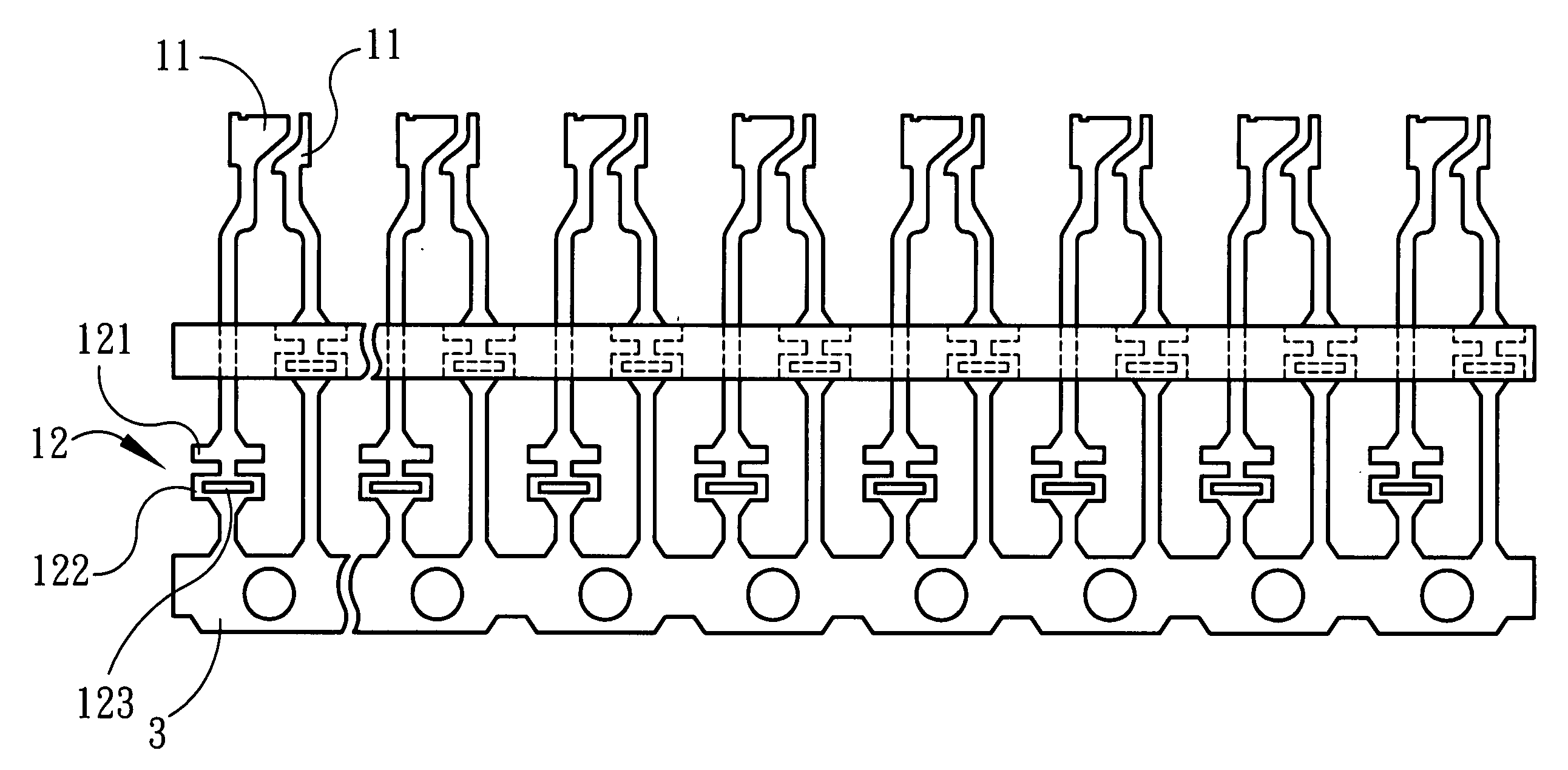
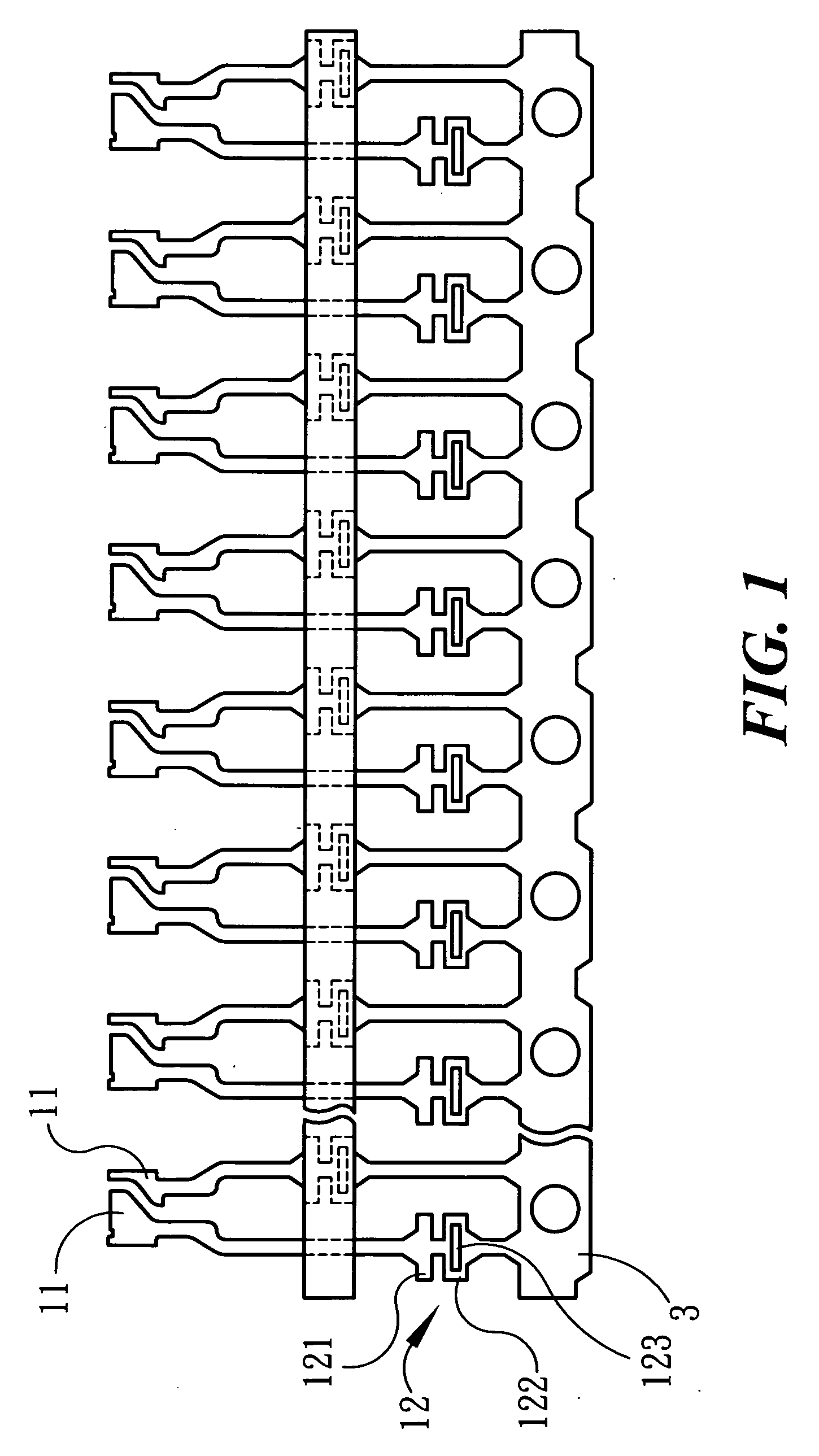
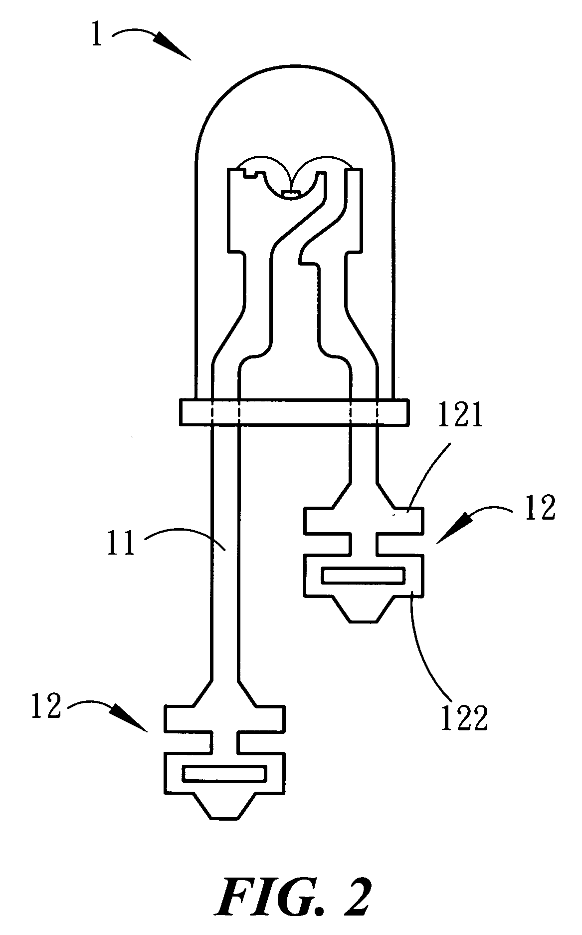
[0018]Referring to FIG. 1, the LED decorative lighting structure of the present invention comprises a plurality of LEDs 1 which being connected in series or parallel with conductors 2. Each of the LED 1 is provided with two conductor blades 11 cut down from a string of the same material 3 so that a large numbers of conductor blade 11 can be directly formed from the same material strip 3 thereby the production line is simplified and the production cost curtailed. Each conductor blade 11 has a terminal 12 which further includes a holding strip 121 and an electric conducting strip 122. The holding strip 121 is for fixing the outer insulation sheath 21 of the circuit conductor 2 by pressing thereon; while the conducting strip 122 is for fixing and making connection with the metallic stranded core elements 22 of the circuit conductor 2. The holding strips 121 and the conducting strips 122 in two adjacent conductor blades 11 are disposed in different height with each other so as to avoid ...


PUM


Abstract

A LED decorative lighting structure comprises a plurality of LEDS. Each LED has two electric conductor blades which being directly made by cutting down from a strip of the same material. Each of the two conductor blades is equipped with a terminal which further includes a holding strip and an electric conducting strip. The holding strip is for fixing an outer insulation sheath of a conductor by pressing on it; while the conducting strip is for fixing and making connection with the metallic stranded core wires of the conductor. The holding strips and the electric conducting strips in both conductor blades are disposed in different height with each other so as to avoid shortcircuiting by accidental contact. The plurality of LED constructed as such can be arranged in series/parallel connection thereby forming a desired configuration of the LED decorative lighting structure according to the present invention.

Description

BACKGROUND OF THE INVENTION[0001]1. Field of the Invention[0002]The present invention relates to a LED decorative lighting structure, in particular, to a LED decorative lighting structure which has a firm construction with an excellent water tight and dust protection ability in compliance with IP66 international standards applicable to any environmental condition, and can be fabricated with a low production cost.[0003]2. Description of the Prior Art[0004]Conventionally, a decorative lighting structure is assembled with a string of miniature lamps connected in series or parallel so as to glitter or flash. In the case of an art exhibition, festival or ceremonial banquet, it always plays an important roll in the occasion.[0005]A miniature incandescent lamp is the hero in the traditional decorative lighting. It has the inherent disadvantages of considerably large size, high power consumption accompanied with a high temperature, low resistance to the weather condition if installed in out...

Claims


Application Information

Patent Timeline
Patent Type & Authority Applications(United States)
IPC IPC(8): F21V29/00
CPCF21S4/001F21Y2101/02H01L2924/12041H01L24/97H01L2224/48247H01L2224/48091H01L2924/00012F21S4/10F21Y2115/10H01L2224/48257
Inventor CHAN, TSUNG-WEN
Owner CHAN KK
Why Eureka
Try Eureka