Exhaust gas purifying system for internal combustion engine

Inactive Publication Date: 2003-03-20
KOMATSU LTD
View PDF2 Cites 58 Cited by
  • Summary
  • Abstract
  • Description
  • Claims
  • Application Information

AI Technical Summary

Problems solved by technology

Such a carrier has many limitations in manufacturing, so that it is difficult to manufacture a carrier having a remarkably large cross-sectional shape.
However, if a plurality of carriers are arranged in parallel, the cross-sectional area of the whole carrier increases, so that a large space for arranging the carriers must be secured in an engine room, which presents a problem of hindering the downsizing of equipment.
Therefore, there still remains a prob

Method used


Image

  • Exhaust gas purifying system for internal combustion engine
  • Exhaust gas purifying system for internal combustion engine
  • Exhaust gas purifying system for internal combustion engine

Examples


Example

[0044] One embodiment of the present invention will now be described with reference to the accompanying drawings.

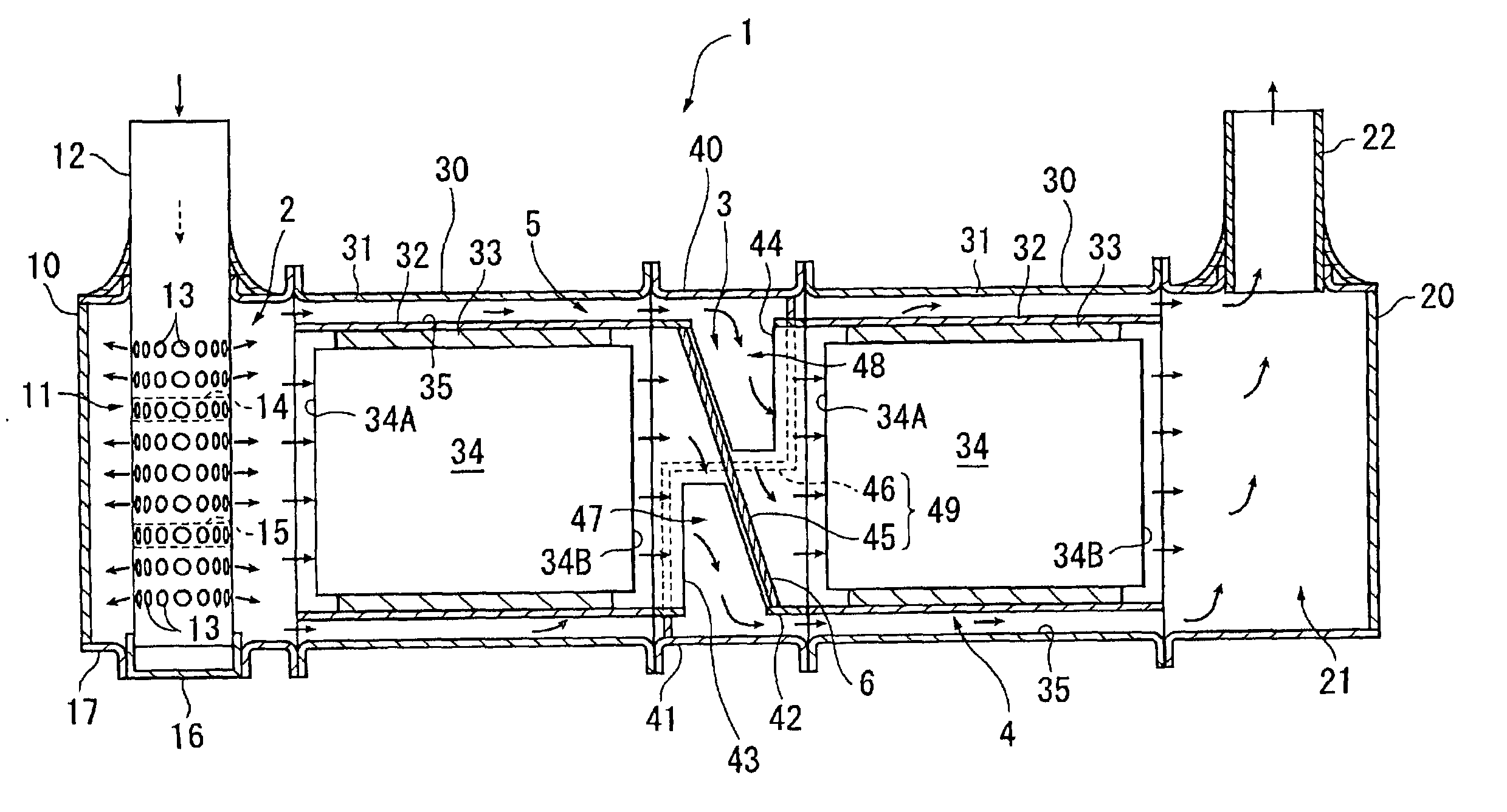
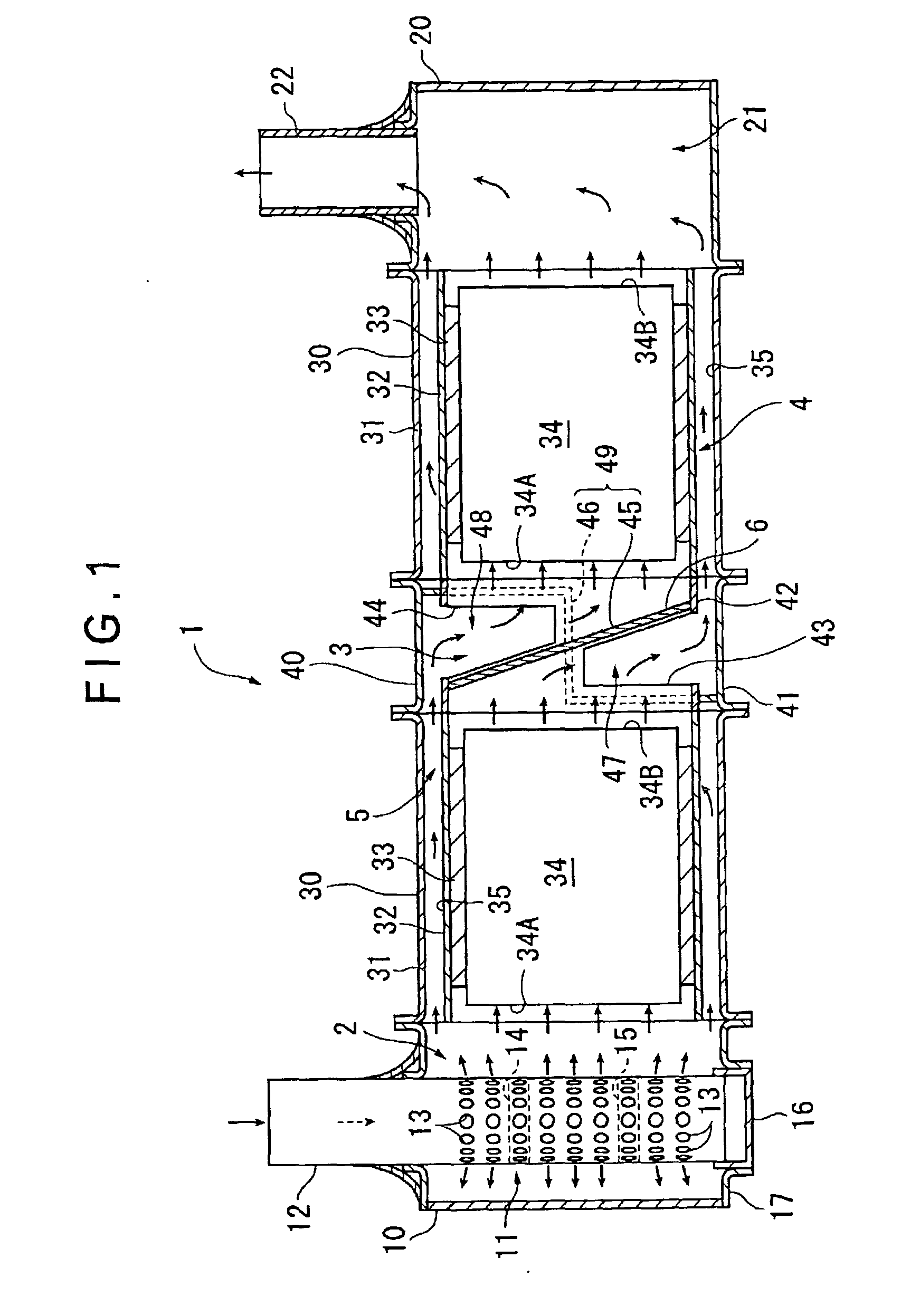
[0045] FIG. 1 shows an exhaust gas purifying system 1 in accordance with one embodiment of the present invention. This exhaust gas purifying system 1 is provided halfway in an exhaust passage of a diesel engine (not shown), one type of an internal combustion engine, to purify exhaust gas emitted from the diesel engine.

[0046] Specifically, the exhaust gas purifying system 1 includes an inlet chamber unit 10 provided on the inflow side of exhaust gas, a combined flow chamber unit 20 provided on the discharge side of exhaust gas, a pair of carrier arrangement units 30 disposed in series along one flow direction of exhaust gas flowing from the inlet chamber unit 10 to the combined flow chamber unit 20, and a split flow unit 40 disposed between the carrier arrangement units 30.

[0047] These units 10, 20, 30 and 40 are formed into a cylindrical shape and are connected to each ot...


PUM

PropertyMeasurementUnit
Flow rateaaaaaaaaaa

Abstract

In an exhaust gas purifying system 1, a pair of carriers 34 is arranged in series along the flow direction of exhaust gas. Approximately a half of the exhaust gas passing through a first distribution flow path 4 flows in the upstream-side carrier 34, and the remaining half of the exhaust gas passing through a second distribution flow path 5 flows in the downstream-side carrier 34. Therefore, the capacity of the whole of the paired carriers 34 can be substantially doubled as in the case where the carriers 34 are arranged in parallel, so that the function as the exhaust gas purifying system 1 can be improved.

Description

[0001] 1. Field of the Invention[0002] The present invention relates to an exhaust gas purifying system for an internal combustion engine and, more particularly, to an exhaust gas purifying system provided in an exhaust passage of the internal combustion engine to purify exhaust gas.[0003] 2. Description of Related Art[0004] Conventionally, it is known that an exhaust gas purifying system is provided in an exhaust passage of an internal combustion engine to collect particulates (particulate substances) in exhaust gas emitted from the internal combustion engine such as a diesel engine or to reduce NOx content.[0005] As an exhaust gas purifying system for collecting particulates, a system provided with an exhaust emission after-treatment device consisting of a diesel particulate filter (hereinafter referred to as a DPF) has been developed.[0006] As an exhaust gas purifying system for reducing NOx content, a system provided with an exhaust emission after-treatment device consisting of ...

Claims


Application Information

Patent Timeline
IPC IPC(8): F01N3/02F01N3/021F01N3/022F01N3/023F01N3/031F01N3/035F01N3/08F01N3/18F01N3/20F01N3/24F01N3/28F01N13/04F01N13/18
CPCF01N3/0814F01N3/0842F01N3/2853F01N13/18F01N2470/02F01N2470/18Y10S55/30F01N13/011F01N13/017F01N3/021
Inventor NISHIYAMA, TOSHIHIKOWAKAMOTO, KOUTAROUEMORI, NOBUHIKO
Owner KOMATSU LTD
Why Eureka
Try Eureka