Wireless location using multiple location estimators

a technology of multiple location estimation and wireless communication, applied in direction finders using radio waves, instruments, wireless communication, etc., can solve the problems of high cost, special purpose electronics required, and system effectiveness generally only in line-of-sight conditions, so as to achieve effective and straightforward resolution of ambiguities and/or conflicts between location estimations

Inactive Publication Date: 2001-06-19
TRACBEAM
View PDF170 Cites 1292 Cited by
  • Summary
  • Abstract
  • Description
  • Claims
  • Application Information

AI Technical Summary

Benefits of technology

The present invention relates to a method and system for performing wireless mobile station location. In particular, the present invention is a wireless mobile station location computing method and system that utilizes multiple wireless location computational estimators (these estimators also denoted herein as MS location hypothesizing computational models, "first order models" and / or "location estimating models"), for providing a plurality of location estimates of a target mobile station, wherein ambiguities and / or conflicts between the location estimates may be effectively and straightforwardly resolved. More particularly, the present invention provides a technique for calibrating the performance of each of the location estimators so that a confidence value (e.g., a probability) can be assigned to each generated location estimate. Additionally, the present invention provides a straightforward technique for using the confidence values (probabilities) for deriving a resulting most likely location estimate of a target wireless mobile station.

Problems solved by technology

However, these systems have drawbacks that include high expense in that special purpose electronics are required.
Furthermore, the systems are generally only effective in line-of-sight conditions, such as rural settings.
Radio wave surface reflections, refractions and ground clutter cause significant distortion, in determining the location of a signal source in most geographical areas that are more than sparsely populated.
Moreover, these drawbacks are particularly exacerbated in dense urban canyon (city) areas, where errors and / or conflicts in location measurements can result in substantial inaccuracies.
However, the GPS is impractical in many applications.
Accordingly, inclement weather conditions, such as clouds, terrain features, such as hills and trees, and buildings restrict the ability of the GPS receiver to determine its position.
Furthermore, the initial GPS signal detection process for a GPS receiver is relatively long (i.e., several minutes) for determining the receiver's position.
Such delays are unacceptable in many applications such as, for example, emergency response and vehicle tracking.
However, in the worst-case scenario both fading margins are simultaneously exceeded, thus causing a fading margin overload.

Method used


Image

  • Wireless location using multiple location estimators
  • Wireless location using multiple location estimators
  • Wireless location using multiple location estimators

Examples


embodiment

MS Status Repository Embodiment

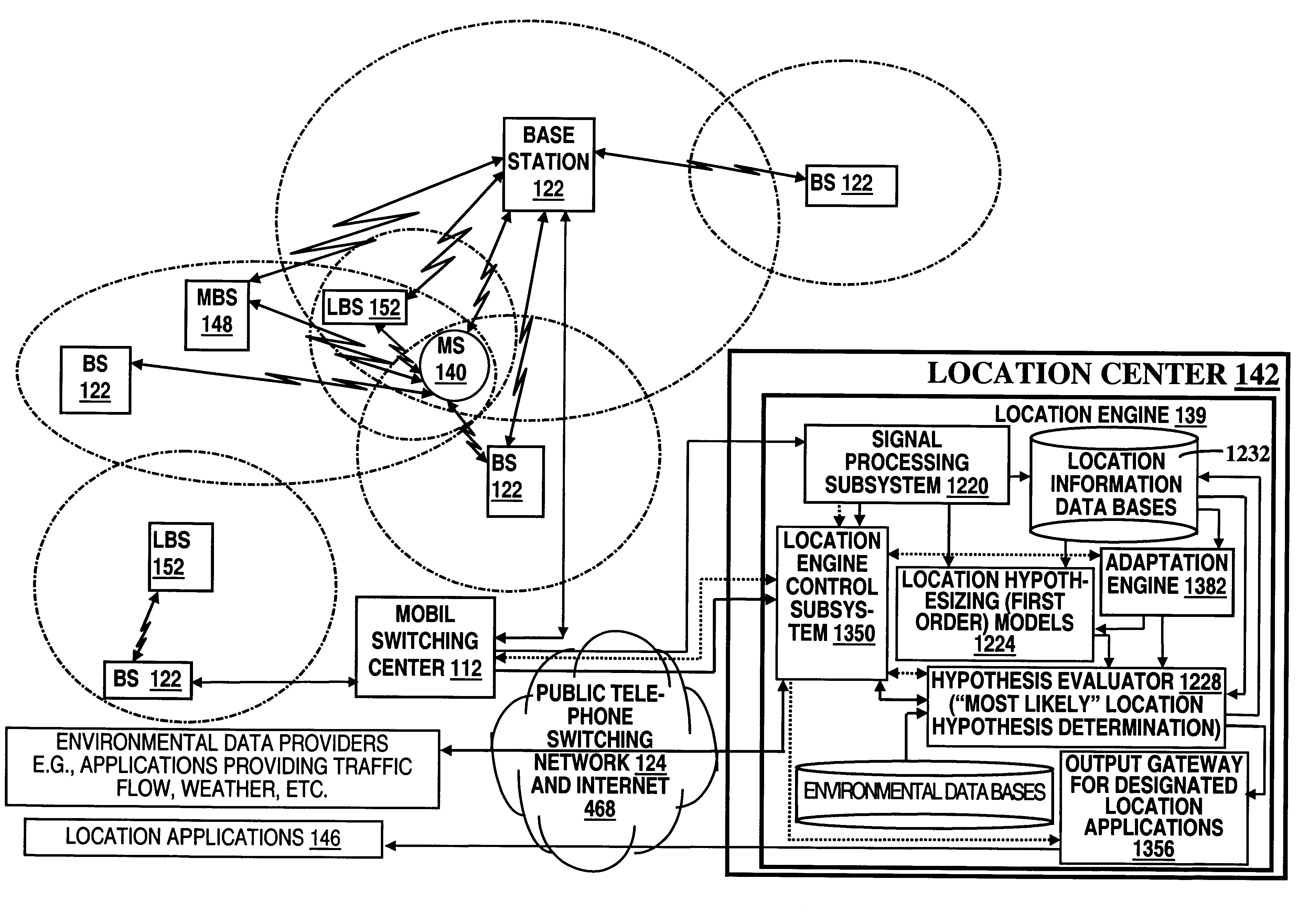
The MS status repository 1338 is a run-time storage manager for storing location hypotheses from previous activations of the location engine 139 (as well as the output target MS location estimate(s)) so that a target MS may be tracked using target MS location hypotheses from previous location engine 139 activations to determine, for example, a movement of the target MS between evaluations of the target MS location. Thus, by retaining a moving window of previous location hypotheses used in evaluating positions of a target MS, measurements of the target MS's velocity, acceleration, and likely next position may be determined by the location hypothesis analyzer 1332. Further, by providing accessibility to recent MS location hypotheses, these hypotheses may be used to resolve conflicts between hypotheses in a current activation for locating the target MS; e.g., MS paths may be stored here for use in extrapolating a new location

Mobile Base Station Location S...


PUM


Abstract

A location system is disclosed for commercial wireless telecommunication infrastructures. The system is an end-to-end solution having one or more location centers for outputting requested locations of commercially available handsets or mobile stations (MS) based on, e.g., CDMA, AMPS, NAMPS or TDMA communication standards, for processing both local MS location requests and more global MS location requests via, e.g., Internet communication between a distributed network of location centers. The system uses a plurality of MS locating technologies including those based on: (1) two-way TOA and TDOA; (2) pattern recognition; (3) distributed antenna provisioning; (5) GPS signals, (6) angle of arrival, (7) super resolution enhancements, and (8) supplemental information from various types of very low cost non-infrastructure base stations for communicating via a typical commercial wireless base station infrastructure or a public telephone switching network. Accordingly, the traditional MS location difficulties, such as multipath, poor location accuracy and poor coverage are alleviated via such technologies in combination with strategies for: (a) automatically adapting and calibrating system performance according to environmental and geographical changes; (b) automatically capturing location signal data for continual enhancement of a self-maintaining historical data base retaining predictive location signal data; (c) evaluating MS locations according to both heuristics and constraints related to, e.g., terrain, MS velocity and MS path extrapolation from tracking and (d) adjusting likely MS locations adaptively and statistically so that the system becomes progressively more comprehensive and accurate. Further, the system can be modularly configured for use in location signing environments ranging from urban, dense urban, suburban, rural, mountain to low traffic or isolated roadways. Accordingly, the system is useful for 911 emergency calls, tracking, routing, people and animal location including applications for confinement to and exclusion from certain areas.

Description

The present invention is directed generally to a system and method for locating people or objects, and in particular, to a system and method for locating a wireless mobile station using a plurality of activated mobile station location estimators.The present invention is directed generally to a system and method for locating people or objects, and in particular, to a system and method for locating a wireless mobile station using a plurality of mobile station location estimators. More generally, the present invention is directed to a computational system and method for calibrating the relative performance of multiple models, wherein each such model is capable of being activated for generating hypotheses (e.g., estimates and / or predictions) of an unknown condition such as the location of wireless mobile station. Additionally, the present invention is directed to a computational system and method for generating enhanced hypotheses of the unknown condition, wherein the model generated hy...

Claims


Application Information

Patent Timeline
Patent Type & Authority Patents(United States)
IPC IPC(8): G01S1/02G01S1/00G01S5/00G01S5/02H04Q7/38G01S5/06G01S19/09G01S19/46H04W64/00
CPCG01S1/028G01S5/0009G01S5/02G01S5/0205G01S5/021G01S5/0252H04W64/00G01S5/0018G01S5/0054G01S5/06G01S2205/006G01S2205/008H04W88/005H04W4/029G01S5/0244G01S2205/06
Inventor DUPRAY, DENNIS J.
Owner TRACBEAM
Why Eureka
Try Eureka