Method and apparatus for manufacturing AC-generator's stator for vehicle

a technology of ac generator and stator, which is applied in the direction of forging/pressing/hammering apparatus, magnetic bodies, applications, etc., can solve the problem that the manufacturing method does not provide such high accuracy

Inactive Publication Date: 2001-06-26
DENSO CORP
View PDF16 Cites 99 Cited by
  • Summary
  • Abstract
  • Description
  • Claims
  • Application Information

AI Technical Summary

Problems solved by technology

However, it is difficult for this me

Method used


Image

  • Method and apparatus for manufacturing AC-generator's stator for vehicle
  • Method and apparatus for manufacturing AC-generator's stator for vehicle
  • Method and apparatus for manufacturing AC-generator's stator for vehicle

Examples


first embodiment

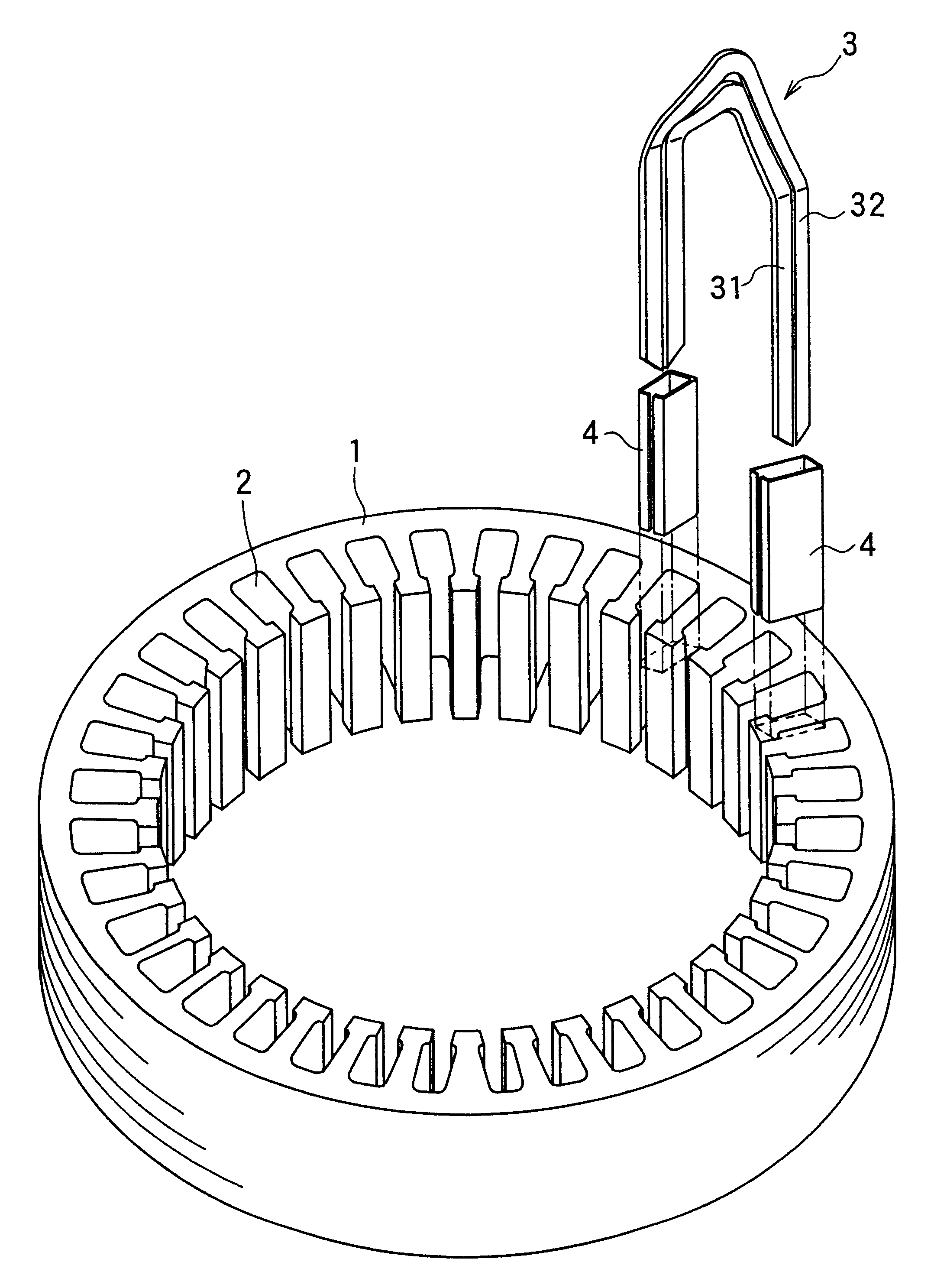
A method and an apparatus for manufacturing an AC generator's stator for a vehicle according to a first embodiment of the present invention are described in detail with reference to FIGS. 1-14. FIG. 1 is perspective view of a stator core, insulators and segments used in manufacturing a stator.

A plurality of U-shaped conductor segments 3 (hereinafter referred to as "the segments") are respectively inserted into plural slots 2 formed on a cylindrical stator core in the circumferential direction, and edge portions of the segments are connected to form a stator winding.

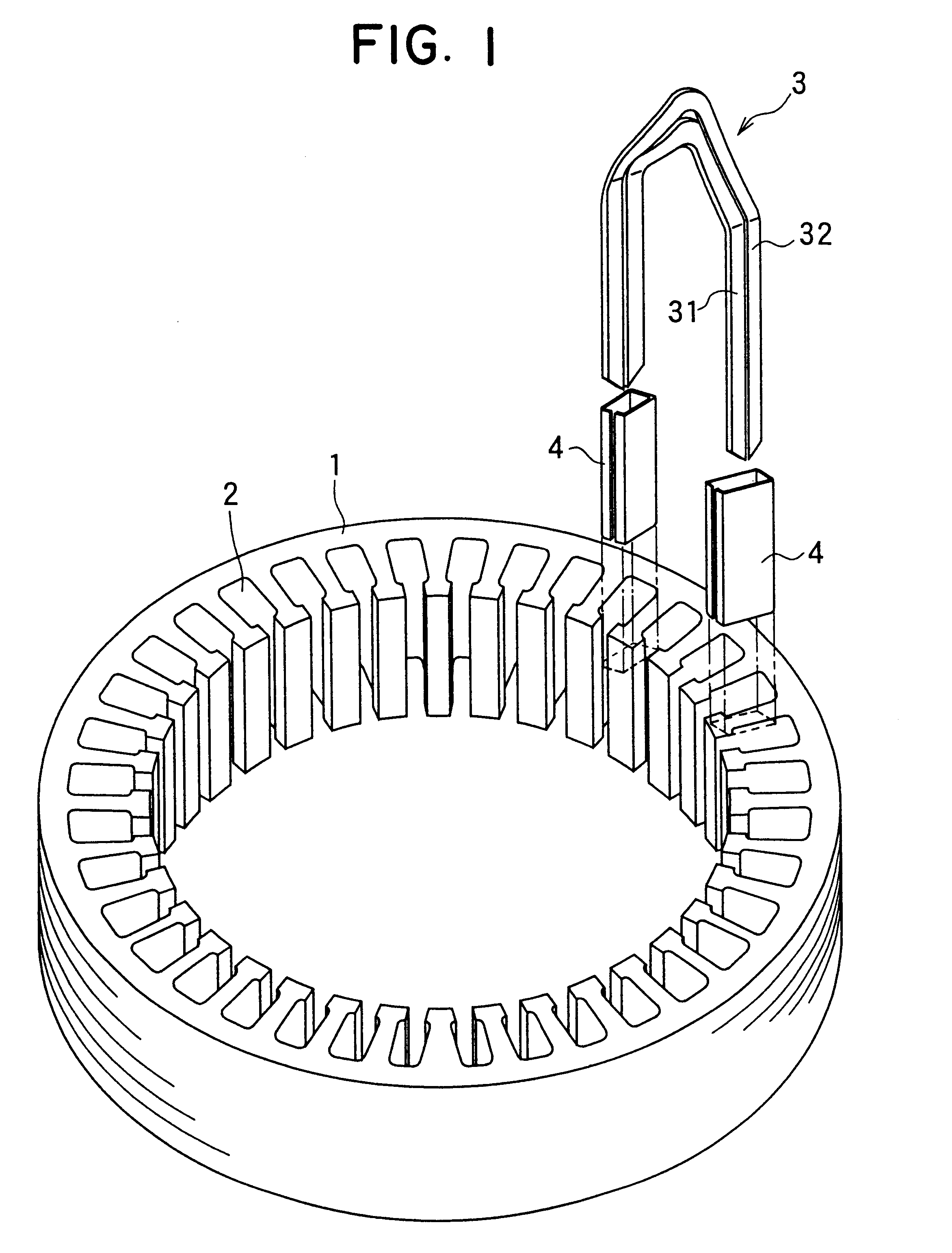
A copper wire having a rectangular-cross-section is cut into segment having a prescribed length, which is bent to form the U-shaped segments 3. As shown in FIG. 2, there are two kinds of U-shaped segments 3, a big segment and a small segment. The turn portion 32a of the big segment 32 surrounds the turn portion 31a of the small segment 31. Edge portions 32d, 32e of the big segment 32 have tapered surfaces descending from ...

second embodiment

FIG. 15 illustrates a step of press-fitting the segments into the slots by use of a stator manufacturing apparatus according to a second embodiment. The method according to the second embodiment is almost the same as the first embodiment except a step of press-fitting the segments into the slots.

In the second embodiment, the assembling tool 20 has an axial-holder 24 of the segments. The axial-holder 24 is disposed on the side of the stator core opposite the side thereof from that the edge portions 31d, 31e, 32d, 32e of the segments 3 are inserted to hold the edge portions 31d, 31e, 32d, 32e of the segments 3.

In the step of press-fitting, the segments 3 are pressed by the presser while the segments are held at the edge portions 31d, 31e, 32d, 32e by the axial-holder 24.

The segments 3 are press-fitted into the slots 2 while the segments are supported at both the edge portions 31d, 31e, 32d, 32e and the turn portions 31a, 32a. The edge portions 31d, 31e, 32d, 32e are held to insert the...


PUM


Abstract

The object of the present invention is to provide a method and an apparatus for manufacturing a stator to improve accuracy in inserting conductor segments (3, 31, 32) into slots (2). The apparatus according to the present invention comprises a conductor holder (21, 22) holding the conductor segments (3, 31, 32) and an axial-moving-mechanisms (214) moving the conductor holder (21, 22) relative to a stator core (1) in an axial direction. The conductor holder (21, 22) holds straight portions (31b, 31c, 32b, 32c) of the conductor segments (3, 31, 32) to be inserted into the slots (2) from one end of the stator core (1).

Description

1. FIELD OF THE INVENTIONThe present invention relates to a method and an apparatus for manufacturing an AC generator's stator for a vehicle such as a passenger car or a truck.2. PRIOR ARTSince the AC generator for a vehicle has been required to be more powerful, the resistance of the stator winding is required to be lower and lower, thereby reducing the length of the magnet wire.It is well known that a plurality of U-shaped conductor segments are respectively inserted into slots of a stator core in the same direction and are connected with each other to form a stator winding, thereby increasing the output power of a vehicular AC generator, as disclosed in International Publication Number WO 92 / 06527 (1992). Because U-shaped conductor-segments can be disposed very regularly in this structure, the slot-space factor and the output power thereof can be increased.Before turn portions of conductor segments are twisted in a manufacturing process of the above conventional structure, an ann...

Claims


Application Information

Patent Timeline
IPC IPC(8): H02K15/06H02K15/00H02K15/04
CPCH02K15/0428H02K15/064Y10T29/53143Y10T29/49071Y10T29/5137Y10T29/49194Y10T29/49009Y10T29/49073
Inventor MAEDA, KAZUTAKATAKAHASHI, MAKOTOSUGIYAMA, MASARUKAMAKURA, YOUICHISUKO, NOBUO
Owner DENSO CORP
Why Eureka
Try Eureka