Cable conduit

a cable conduit and cable technology, applied in the field of cable conduits, can solve the problems of increasing the cost and complexity of using this cable conduit, and achieve the effect of simple and rapid operation

Inactive Publication Date: 2001-07-03
SOC DE CONSTR ELECTRIQUES DE LA SEINE CES
View PDF17 Cites 36 Cited by
  • Summary
  • Abstract
  • Description
  • Claims
  • Application Information

AI Technical Summary

Benefits of technology

As a result of this arrangement, there is no need for any special costly or complex fixtures for running cables into and out from the cable conduit. Furthermore, the tongue can be folded back on itself to free up a cut-out passage for the cable in a simple

Problems solved by technology

The known cable conduit of this type has a disadvantage in that it requires special accessories at points where t

Method used


Image

  • Cable conduit
  • Cable conduit

Examples


Embodiment Construction

The same references are used to denote the same or similar elements in the drawings.

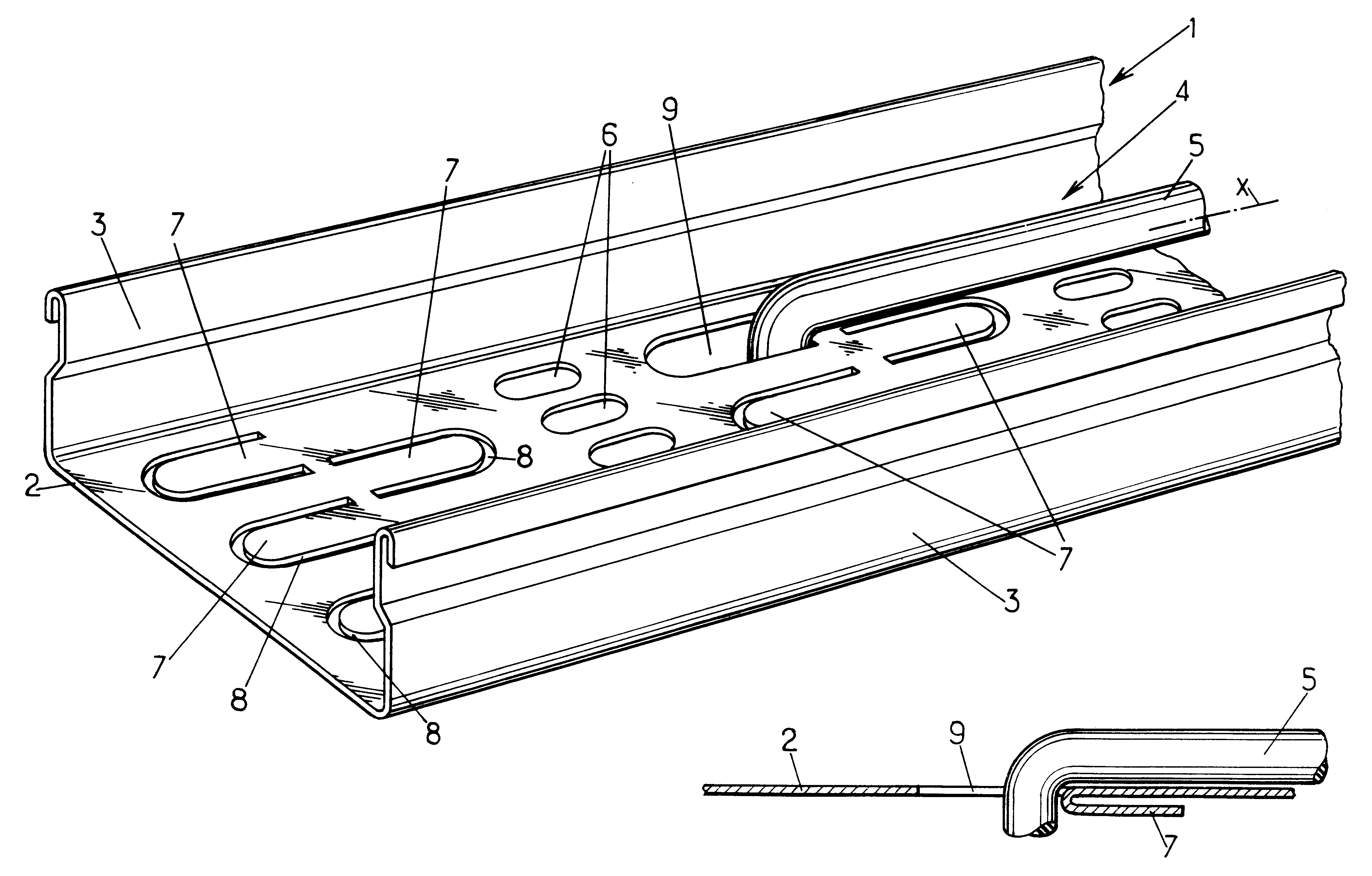
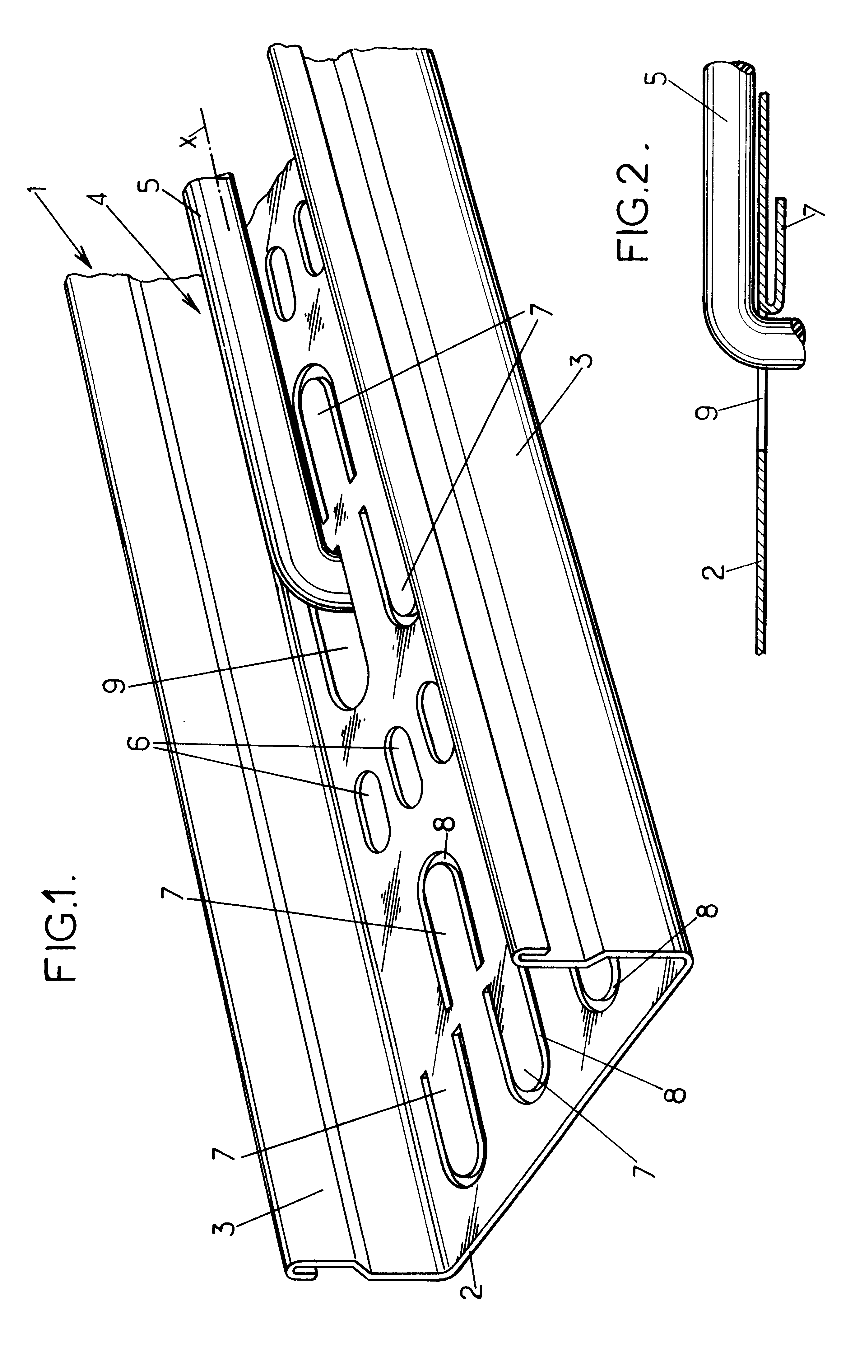
FIG. 1 illustrates a cable conduit 1 which is a metal section of a U-shaped cross-section having a base 2 and two side wings 3 which, depending on the circumstances, may be closed off by a cover (not illustrated). The section 1 bounds an internal space 4 designed to receive one or more cables 5, each extending in the longitudinal direction X of the cable conduit.

The cable 5 is secured inside the cable conduit 1, generally by means of flexible clamping collars (not illustrated), which are located in longitudinal orifices 6 and / or on the tongues 7 bounded by the U-shaped slits provided at least in the base 2 of the cable conduit, as explained in document EP-A-0 813 012 mentioned above.

The tongues 7 preferably extend in the direction X and the U-shaped slits bordering these tongues are preferably arranged at regular intervals spaced close together along the run of cable conduit (the distance between two...


PUM


Abstract

Cable conduit comprising a section of U-shape cross-section, with a base and two wings, the base having U-shape cut-outs each bounding a tongue. One of the tongues is folded back on the base so as to leave free a cable passage opening which enables a cable supported in the cable conduit, to run out from the cable conduit.

Description

The present invention relates to cable conduits.The invention relates more specifically to cable conduits comprising a section with at least one wall in which U-shaped cut-out sections are provided, each delimiting a tongue.Document EP-A-0 813 012 describes an example of this type of cable conduit, in which the tongues are used for attaching cable fixing collars.The known cable conduit of this type has a disadvantage in that it requires special accessories at points where the cables are run out from the cable conduit, which increases the cost and complexity of using this cable conduit.OBJECTS AND SUMMARY OF THE INVENTIONThe specific purpose of this invention is to overcome this drawback.To this end, the invention proposes a cable conduit of the type in question which is essentially characterised in that at least one of said tongues is folded back on itself so as to leave free a cut-out portion through which cable can be passed through the wall of the cable conduit.As a result of thi...

Claims


Application Information

Patent Timeline
IPC IPC(8): H02G3/04
CPCH02G3/045
Inventor DUFOURG, BERNARD
Owner SOC DE CONSTR ELECTRIQUES DE LA SEINE CES
Why Eureka
Try Eureka