
Brake disc for motor-vehicle disc brakes

a technology for brake discs and brake pads, which is applied in the direction of brake types, actuators, friction linings, etc., can solve problems such as inability to operate in an optimal way

Active Publication Date: 2018-10-04
FCA ITAL
View PDF8 Cites 0 Cited by
  • Summary
  • Abstract
  • Description
  • Claims
  • Application Information

AI Technical Summary

Benefits of technology

The present invention aims to provide a brake disc for motor-vehicle disc brakes that reduces the time required for the brakes to bed in after installation. The invention achieves this with a brake disc that can be manufactured with rapid and low-cost operations. The brake disc has a surface irregularity with lines that define sharp edges, which contribute to the initial bedding stage of the brakes. The studies show that this results in a faster initial bedding stage and a reduction of 25% in the time required for bedding as compared to a brake disc without these lines.

Problems solved by technology

It should be added that a general problem of motor-vehicle disc brakes lies in the fact that, after their installation, they are not able to operate in an optimal way until the so-called “bedding” has been carried out of the disc brake pads.

Method used


Image

  • Brake disc for motor-vehicle disc brakes
  • Brake disc for motor-vehicle disc brakes
  • Brake disc for motor-vehicle disc brakes

Examples


Embodiment Construction

[0017]Further characteristics and advantages of the invention will become apparent from the description that follows with reference to the attached drawings, provided purely by way of non-limiting example, wherein:

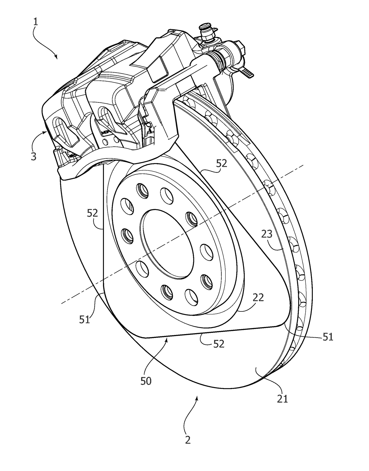
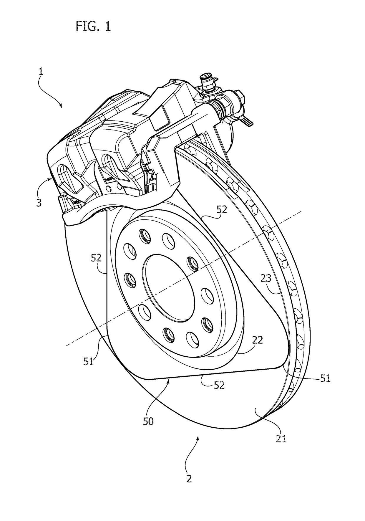
[0018]FIG. 1 is a perspective view of a disc brake assembly including a brake disc according to the invention and a brake caliper associated therewith,

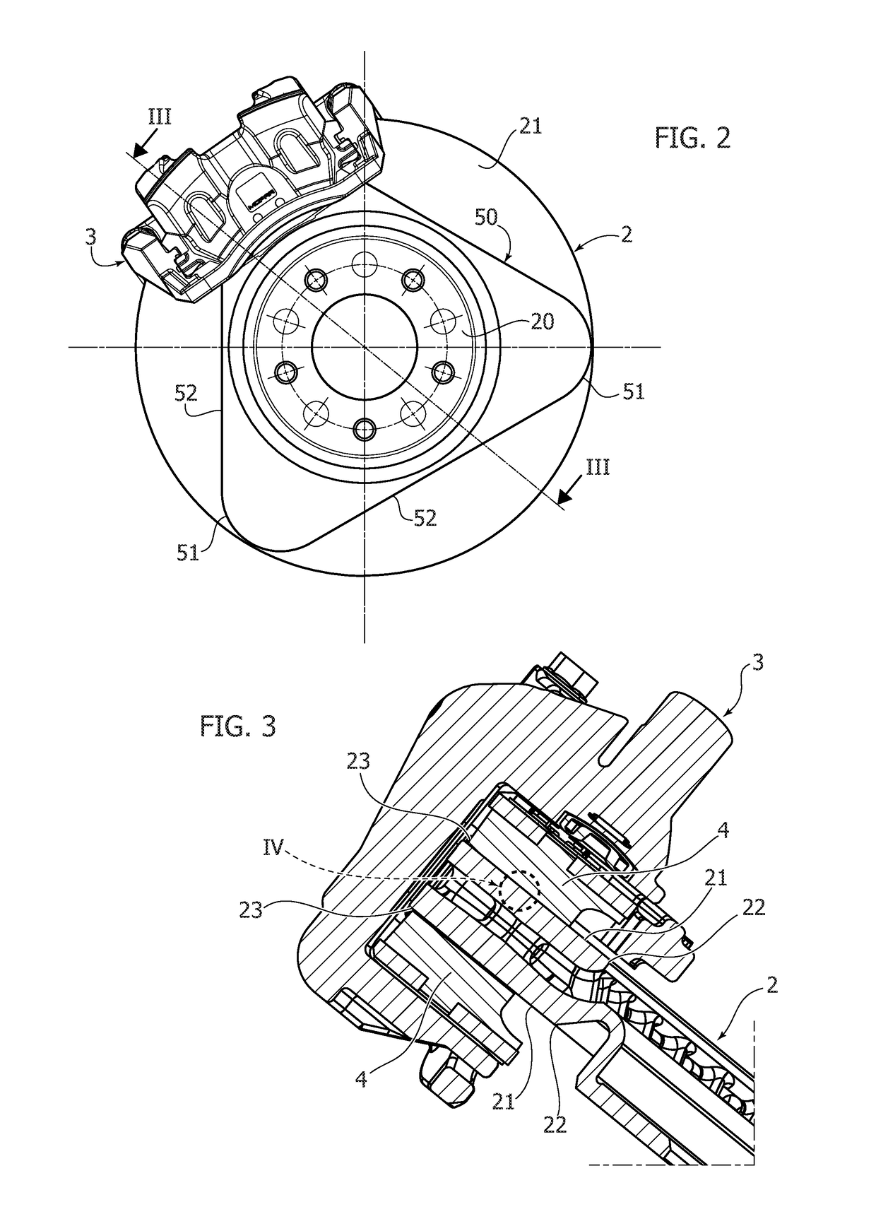
[0019]FIG. 2 is a front view of the disc brake assembly of FIG. 1,

[0020]FIG. 3 is a detail on an enlarged scale of a view in cross-section according to the line III-III of FIG. 2,

[0021]FIG. 4 is a cross-sectional view on a magnified scale of a detail indicated by the arrow IV of FIG. 3, and

[0022]FIG. 5 illustrates a variant of FIG. 4.

[0023]With reference to FIG. 1, the number 1 indicates—in its entirety—a disc brake assembly, including a brake disc 2 and a brake caliper 3 of any known type, provided with brake pads 4 (see FIG. 3) that can be pressed by a respective actuator (not illustrated) against the two opposite faces of...


PUM


Abstract

A brake disc for motor-vehicle disc brakes, includes a body with a hub and two opposite annular planar faces, wherein at least one of these faces is formed with one or more lines defining a surface irregularity, in the form of grooves or ribs, which extend between a radially inner edge and a radially outer edge of the respective face, so as to substantially cover the entire radial extension of the face. A height of the surface irregularity along said lines is less than 0.30 mm, so that during use, the lines defining the surface irregularity disappear, due to wear of the respective face, after an initial fraction of the life of the brake disc. During this initial stage, the lines defining the surface irregularity reduce the time necessary to obtain a bedding of the disc brake with respect to a case of a brake disc devoid of the lines.

Description

FIELD OF THE INVENTION[0001]The present invention relates to brake discs for motor-vehicle disc brakes, of the type comprising a body with a hub and two opposite annular planar faces, wherein at least one of these faces is formed with one or more lines defining a surface irregularity, which lines extend between a radially inner edge and a radially outer edge of the respective face, so as to substantially cover the entire radial extension of said face.PRIOR ART[0002]A brake disc of the type indicated above is described for example in U.S. Pat. No. 6,186,293 B1. In brake discs of this type, the aforesaid lines defining a surface irregularity are grooves formed on one or both the main faces of the brake disc.[0003]According to this prior art, the aforesaid grooves fulfil the object of improving the cooling of the brake disc thanks to the increase in the cooling surface and the obtainment of turbulence in the flow of cooling air. In these known solutions, the grooves formed on the faces...

Claims


Application Information

Patent Timeline
IPC IPC(8): F16D65/12
CPCF16D65/127F16D2250/0076F16D2065/1332F16D2065/1328F16D2069/004
Inventor BADINO, RENATOLUCA, STEFANO
Owner FCA ITAL
Learn More