
Protective device for an air filter, in particular of a generating set, comprising portions to assemble radially on the filter

a protection device and air filter technology, which is applied in the direction of cartridge filters, stationary filtering elements, containers, etc., can solve the problems of generating a greater quantity of waste, unable to separate the case and filter, and consuming a lot of time, and achieves the effect of low cos

Active Publication Date: 2010-11-18
CUMMINS FILTRATION INC
View PDF2 Cites 0 Cited by
  • Summary
  • Abstract
  • Description
  • Claims
  • Application Information

AI Technical Summary

Benefits of technology

[0033]These economic advantages are combined with the fact that a protective device according to an embodiment of the invention can be realized at less cost compared to the solutions of prior art, the latter entailing simple and rapid operations of mounting (compared to the operations of mounting protective cases for filters of “heavy duty” sets mentioned hereinabove.
[0037]Furthermore, such means contribute in facilitating the setting up of the portions of the case on the filter in order to install it.
[0049]The portions can as such be manufactured at low cost, in particular by moulding of a plastic material.

Problems solved by technology

In certain cases, this operation is rendered tedious and even impossible, due to the presence of obstacles (such as equipment and / or portions of structures) in the immediate vicinity of the generating set.
However, the disadvantage of this technique is that the case and the filter cannot be separated.
Consequently, each filter change tends to generate a quantity of waste that is greater than the replacing of the filter alone.
In addition, the one-piece case / filter unit is a relatively expensive part.
Note that the locking and the sealing of the filter in the case are as such obtained using a specific part, which tends to increase the complexity of the unit as well as its cost of manufacture.
A consequence is that according to this technique, it is not provided to mount the filter without the case (the latter forming a means of linking between the filter and the equipment).
However, this technique is not adapted to exterior applications or to very dusty environments, as no protection of the filter is provided.

Method used


Image

  • Protective device for an air filter, in particular of a generating set, comprising portions to assemble radially on the filter
  • Protective device for an air filter, in particular of a generating set, comprising portions to assemble radially on the filter
  • Protective device for an air filter, in particular of a generating set, comprising portions to assemble radially on the filter

Examples


Embodiment Construction

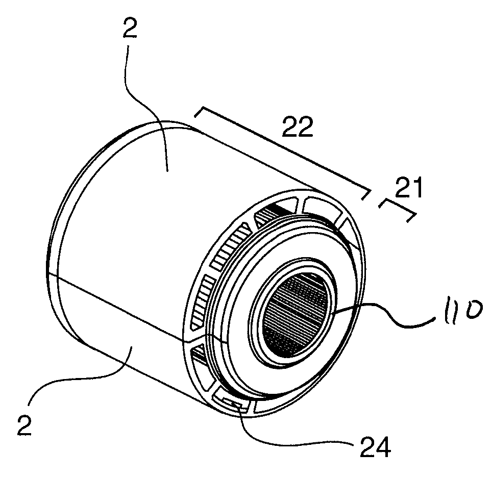
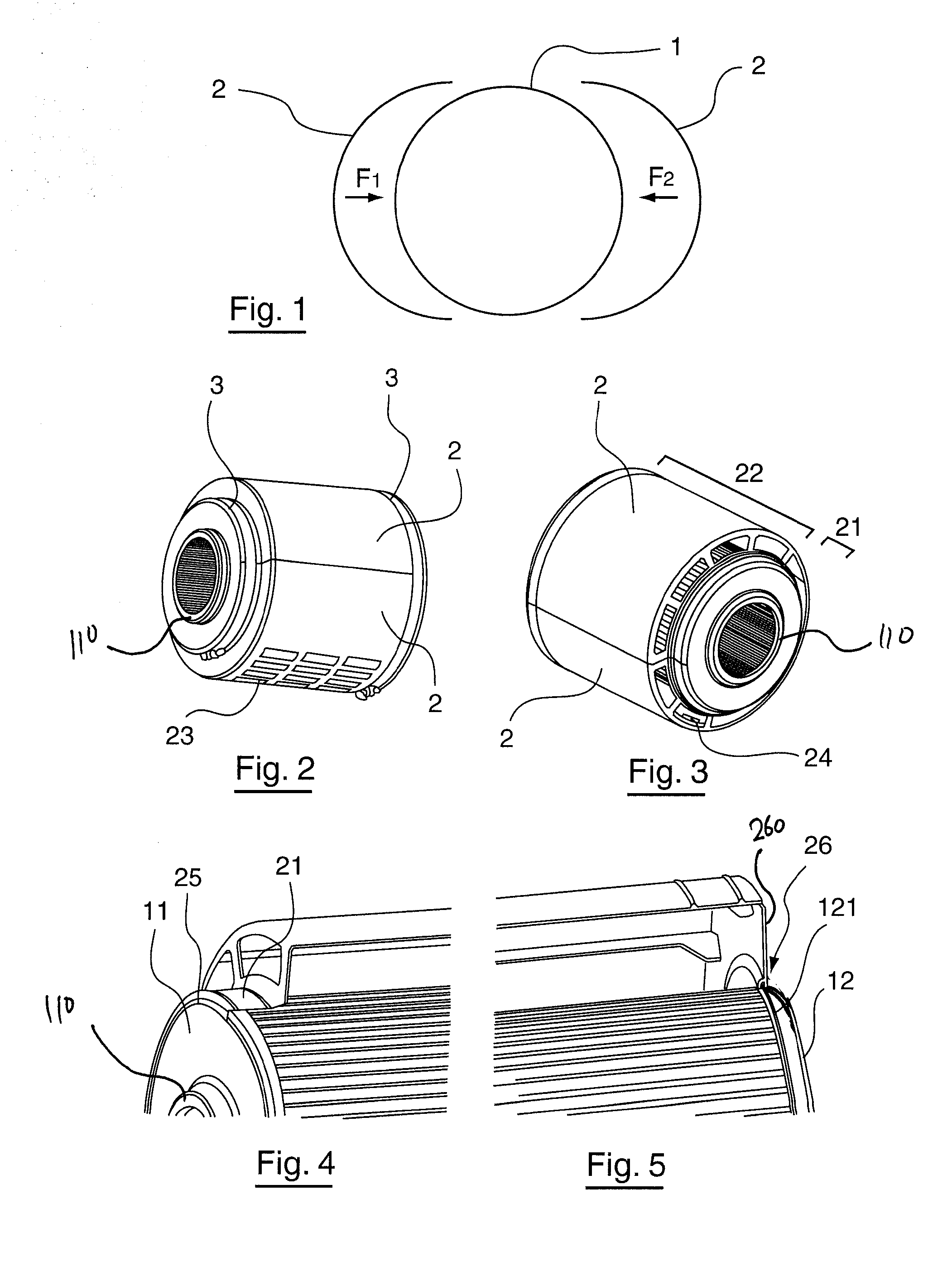
[0058]As mentioned hereinabove, the principle of an embodiment of the invention resides in the fact of designing a protective case of an air filter in the form of portions to secure according to a radial direction in relation to the filter.

[0059]This is shown schematically in FIG. 1, which shows a filter 1 (having conventionally a general cylindrical form forming a section, according to the view in FIG. 1, a circular section) in relation to which a protective device according to an embodiment of the invention comprised of portions 2 is shown.

[0060]Such as is shown clearly, the portions 2 (here in the number of two but which may be of a higher number) are intended to be mounted on the filter by securing them according to the directions indicated by the arrows F1 and F2, i.e. according to radial directions in relation to the filter.

[0061]The number, the form and the dimensions of the portions are defined in such a way that, once mounted on the filter, they fully surround the filter ai...


PUM


Abstract

A protective device is provided for an air filter that is substantially cylindrical and is intended to equip in particular a generating set. The filter is intended to be press fitted to a duct of said set. The protective device includes at least two portions that are securable radially on the filter in order to form a protective case surrounding the filter.

Description

CROSS-REFERENCE TO RELATED APPLICATIONS[0001]This Application is a Section 371 National Stage Application of International Application No. PCT / EP2008 / 050054, filed Jan. 4, 2008 and published as WO 2008 / 095737 on Aug. 14, 2008, not in English.STATEMENT REGARDING FEDERALLY SPONSORED RESEARCH OR DEVELOPMENT[0002]None.THE NAMES OF PARTIES TO A JOINT RESEARCH AGREEMENT[0003]None.FIELD OF THE DISCLOSURE[0004]The disclosure relates to the field of designing and realising equipment and accessories for air filtration. More precisely, the disclosure relates to the protection of air filters, in particular for high-capacity filters such as those mounted on high-power generating sets.[0005]The disclosure applies in particular to generating sets, but can also be applied to other types of equipment requiring a filtered air intake such as marine engines, industrial engines, etc.BACKGROUND OF THE DISCLOSURE[0006]The generating sets implement combustion engines supplied by an air / fuel mixture, with t...

Claims


Application Information

Patent Timeline
IPC IPC(8): B65D85/68
CPCB01D46/0005
Inventor PAGE, EMMANUEL
Owner CUMMINS FILTRATION INC
Learn More