Riser arrangement for offshore vessel and method for installation

Inactive Publication Date: 2001-07-10
SOFEC
View PDF32 Cites 29 Cited by
  • Summary
  • Abstract
  • Description
  • Claims
  • Application Information

AI Technical Summary

Problems solved by technology

There remains an unsolved problem of providing an arrangement and method for its installation of a combined rigid / flexible riser to a turret of a turret moored FPSO.

Method used


Image

  • Riser arrangement for offshore vessel and method for installation
  • Riser arrangement for offshore vessel and method for installation
  • Riser arrangement for offshore vessel and method for installation

Examples


Embodiment Construction

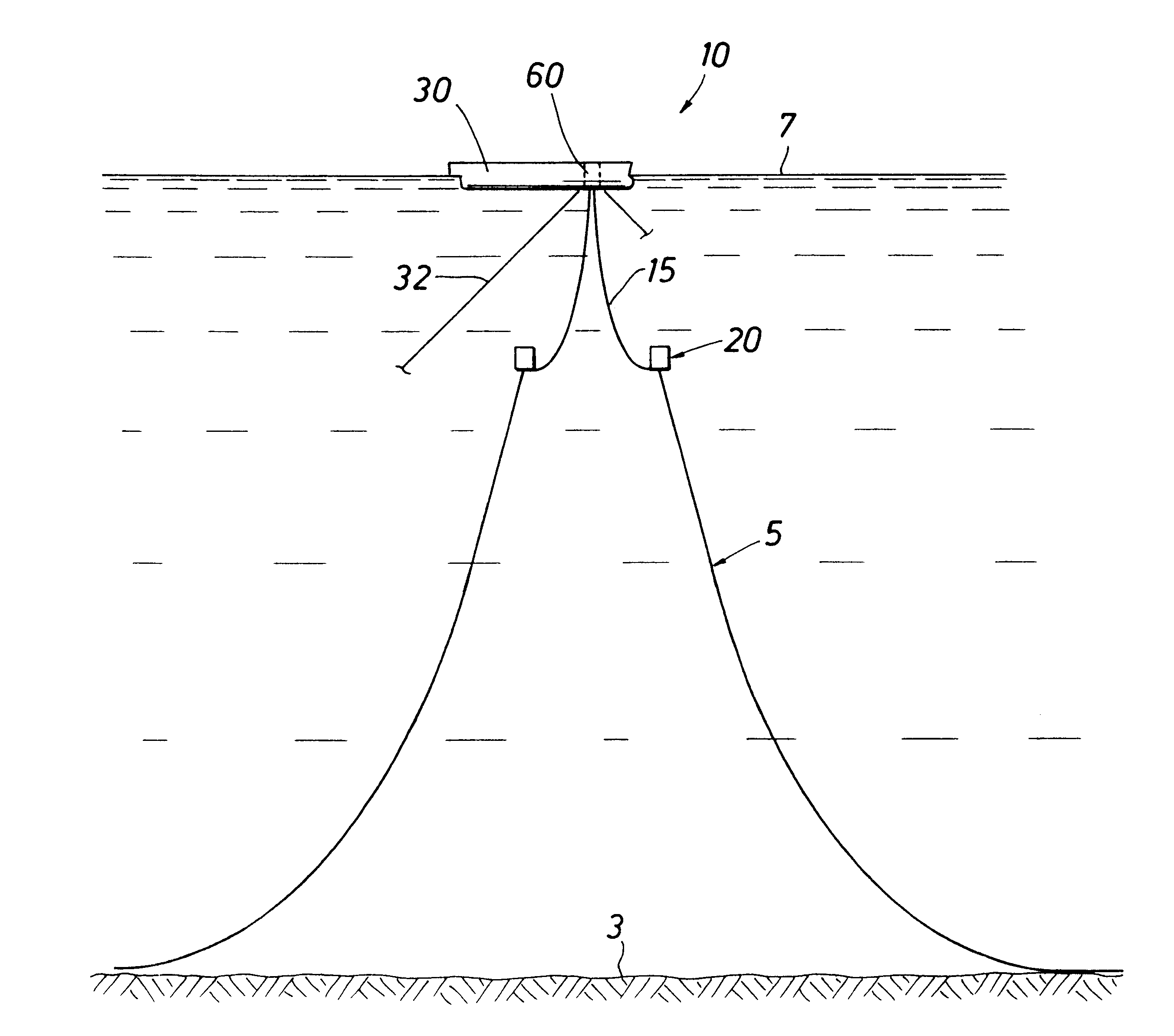
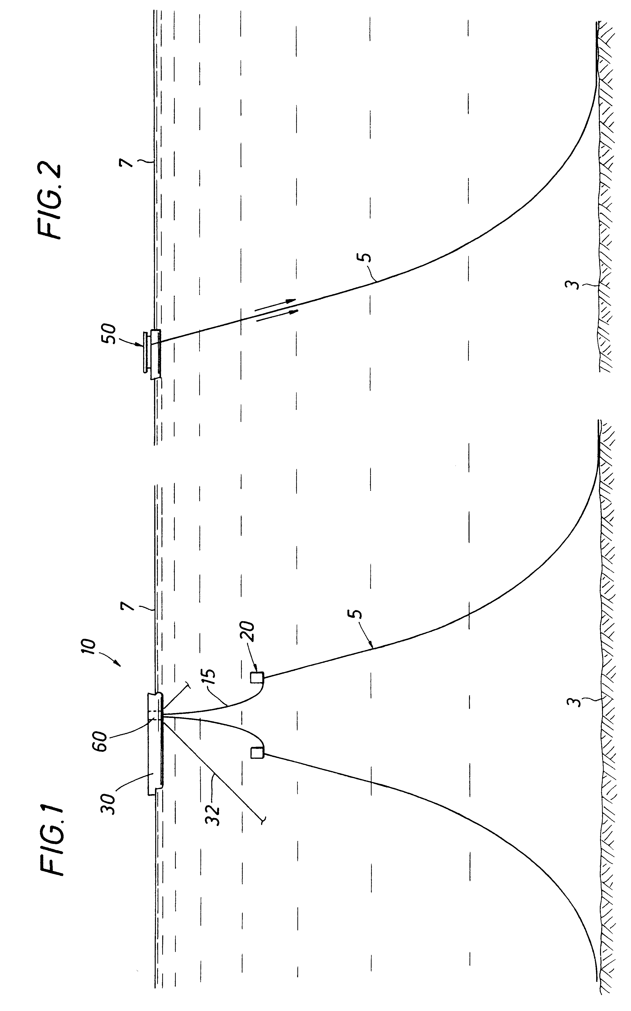
FIG. 1 illustrates the riser system 10 of the invention for providing fluid flow paths between sea bed 3 wells or manifolds (not illustrated) and a turret moored floating vessel 30. The vessel 30 may be any turret moored floating facility equipped for the storage and / or production and offloading of hydrocarbons produced from subsea wells via a riser system. The riser system includes a Steel Catenary Riser (SCR) 5 and a flexible riser 15 which are coupled together at a submerged Steel Catenary Riser Interface Buoy 20 called a SCRIB. The upper end of the flexible riser is connected to a turret interface buoy (See FIGS. 5 and 6) which is secured with the turret 60 of the vessel 30. The SCRIB provides support for the SCR 5 and the lower end of the flexible riser 15. Such SCRIB and the Turret Interface Buoy (TIB) allow the SCR and the flexible riser to be pre-installed prior to the vessel (FPSO) 30 (or other floating facility) being moored on location.

The flexible riser 15 portion of the...


PUM


Abstract

An arrangement and method are disclosed for providing a fluid flow path between a seabed supply of hydrocarbons and a turret moored storage vessel. A steel catenary riser interface buoy provides support for a steel catenary riser and the lower end of a flexible riser. This arrangement allows both risers to be pre-installed prior to arrival of the storage vessel or other floating storage facility. A turret interface buoy, secured to an upper end of the flexible riser is used in the installation process as well as in the hook-up of the riser system to the storage vessel.

Description

1. Field of the InventionThis invention relates generally to mooring arrangements for offshore floating facilities such as floating production, storage and offloading vessels (FPSO). In particular the invention relates to a riser arrangement and method for its installation by which hydrocarbon fluids from subsea wells are transferred to the vessel. Still more particularly the invention relates to a method of installing a riser system in a turret-moored vessel.2. Description of the Prior ArtPrior riser systems have included flexible risers which extend from sea-bed wells or manifolds to the interior of a mooring turret of a FPSO for connection to a fluid swivel mounted on the turret. With deepwater subsea production systems it is advantageous to provide a rigid pipeline for connection at the seabed for connection to subsea wells and manifolds, yet a flexible riser is needed at the vessel for coupling to the turret.U.S. Pat. No. 5,639,187 discloses a marine riser system which combines...

Claims


Application Information

Patent Timeline
Patent Type & Authority Patents(United States)
IPC IPC(8): E21B17/01E21B17/00E21B19/00B63B21/50B63B21/00B63B27/34
CPCE21B19/006E21B17/015B63B21/507B63B2035/448
Inventor KELM, RON L.ETHERIDGE, CHARLES O.LIU, YONGHUI H.
Owner SOFEC
Why Eureka
Try Eureka