
Cassette slant insertion preventing stopper for cassette type recording/reproducing apparatus

a cassette type technology, applied in the direction of web record carrier, magnetic tape recording, instruments, etc., can solve the problems of cassette type recording/reproducing apparatus damage, cassette loading misses, and remarkably bad outward appearance of cassette type recording/reproducing apparatus

Inactive Publication Date: 2001-07-24
SONY CORP
View PDF10 Cites 2 Cited by
  • Summary
  • Abstract
  • Description
  • Claims
  • Application Information

AI Technical Summary

Problems solved by technology

The every-time occurrence of the uncomfortable collision noise as described above causes questions on the quality of products, and thus this is unfavorable.
Therefore, there occurs various problems, for example, the rigidity of the cassette discharge lever 25 and the cam driven lever 28 must be increased.
Therefore, there is such a risk that a next tape cassette 2 is erroneously inserted from the cassette insertion port 4 (i.e., cassette double insertion), another foreign matter is erroneously inserted from-the cassette insertion port 4 or the like.
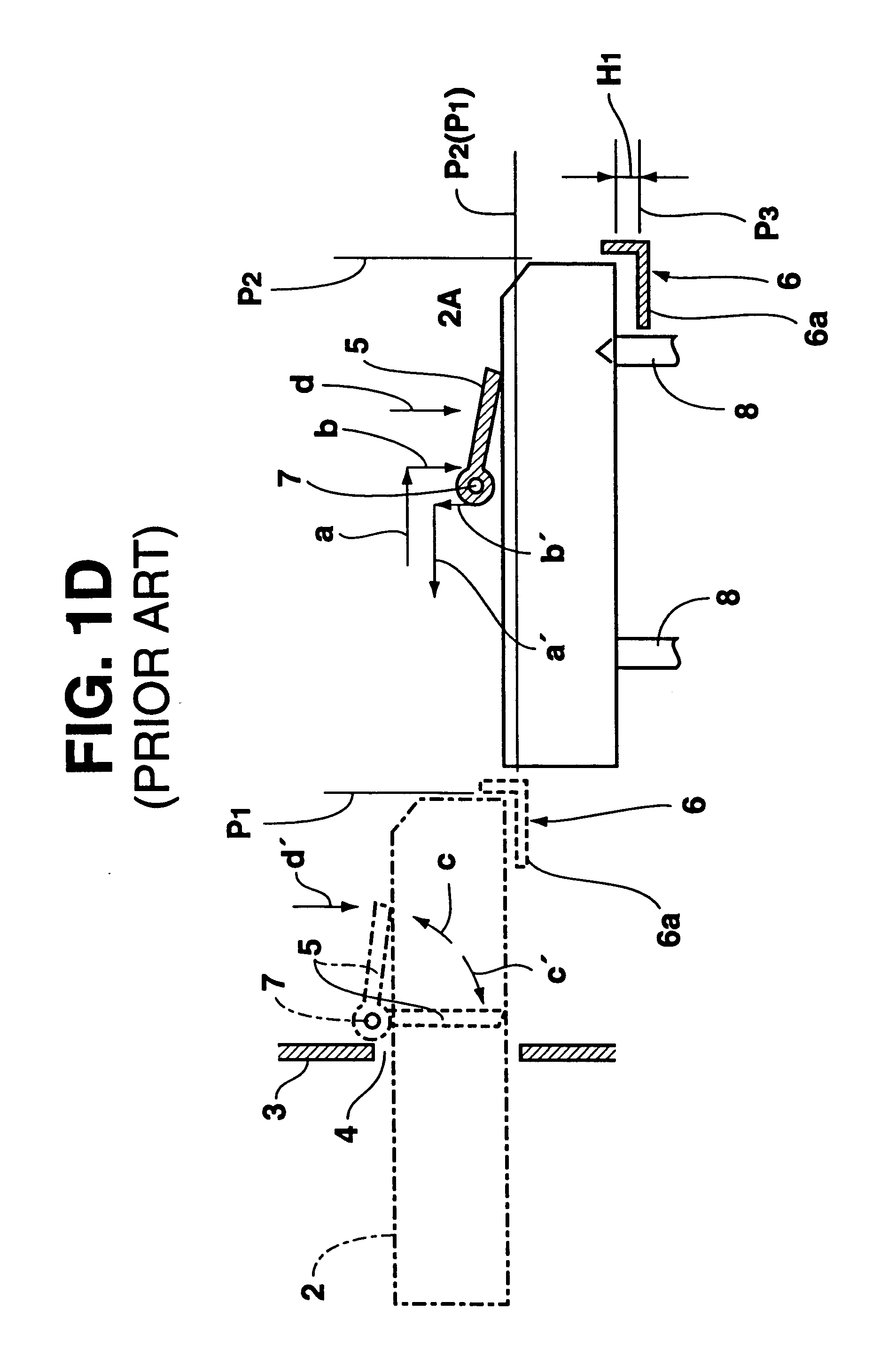
Further, when the tape cassette 2 is loaded to the cassette mount position as indicated by the dotted line of FIG. 1E while obliquely inserted into the cassette stage 6, not only the tape cassette 2 cannot be accurately held by the plural cassette positioning pins 8, but also it runs on to various guides, resulting in a cassette loading miss.
Therefore, the outward appearance of the cassette type recording / reproducing apparatus is remarkably bad.
Therefore, at the subsequent cassette eject time, the tape cassette 1,2 collides against the cassette identifying member 9 and the cassette insertion guide 10, resulting in such a critical accident that that these members are damaged.
Therefore, the number of parts and the number of fabricating steps are remarkably large, and thus the manufacturing cost is remarkably high.
However, the moving range of the detection lever 17 is limited, so that it is very difficult to adjust the switching operation of the small-size tape cassette detecting sensor 22 in the order of OFF-ON-OFF, and this adjustment work causes a remarkable increase in cost.

Method used


Image

  • Cassette slant insertion preventing stopper for cassette type recording/reproducing apparatus
  • Cassette slant insertion preventing stopper for cassette type recording/reproducing apparatus
  • Cassette slant insertion preventing stopper for cassette type recording/reproducing apparatus

Examples


Embodiment Construction

]

Next, the preferred embodiments according to the present invention will be described with reference to FIGS. 3 to 47B.

[Description of Two Types of Tape Cassettes]

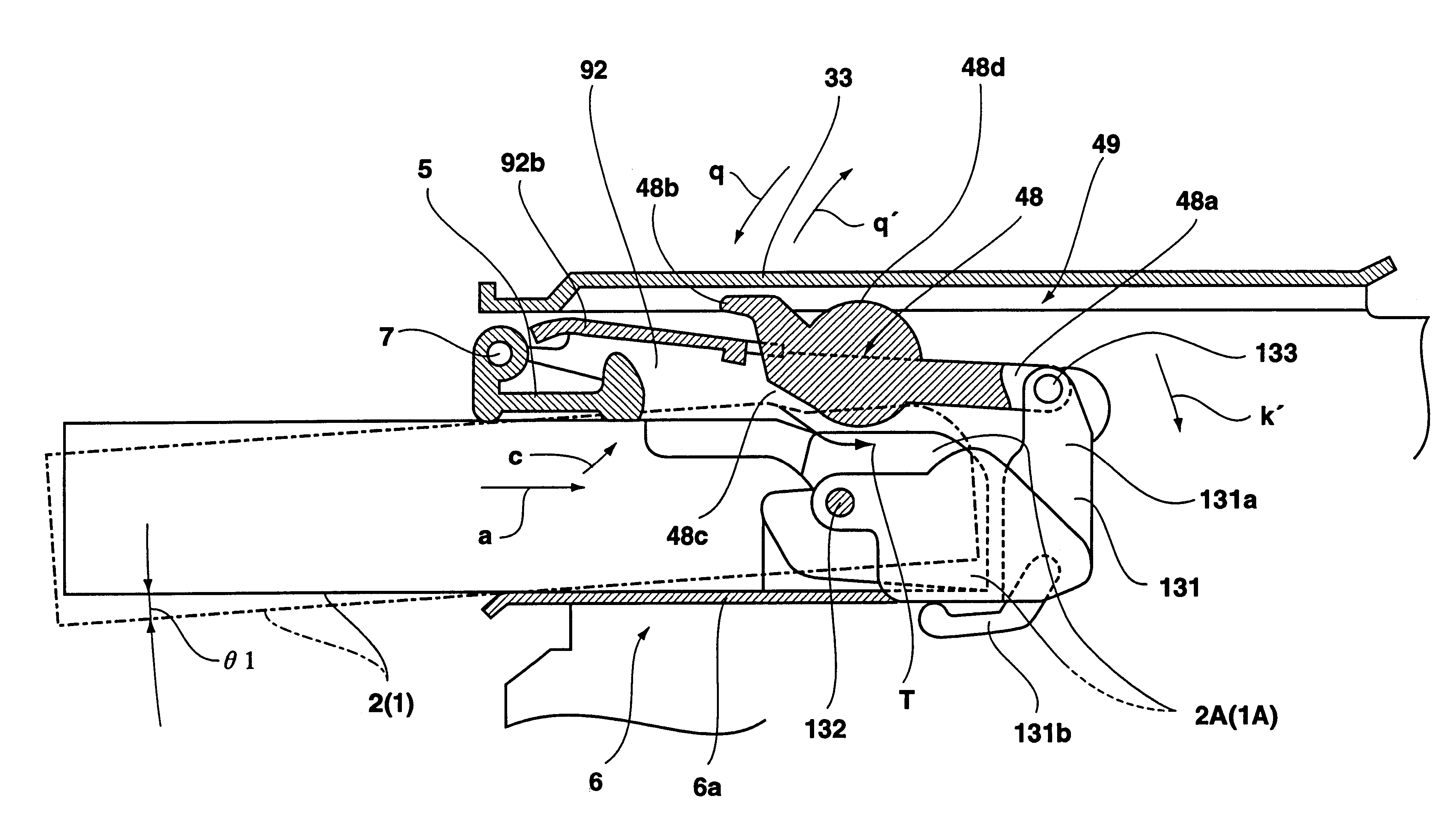
As shown in FIGS. 3 and 4, a magnetic tape 62 which are wound around a pair of right and left tape reels 61 having different diameters is accommodated in each of small-size and large-size tape cassettes 1, 2 which are different in size (the depth in the forward and rearward direction and the width in the right and left direction) D.sub.1 and D.sub.2 and in thickness T.sub.1, T.sub.2. Each of these magnetic tapes 62 is passed along the inner side of the front lid 1A,2A having an inner-and-outer dual structure which is secured to the front end 1a, 2a of the small-size and large-size tape cassettes 1, 2. Further, a cut-out 64 having substantially the same shape is formed at the center portion of the front end 1a, 2a side of the bottom plate 1c, 2c in which a pair of right and left reel table insertion holes 63 of the small-si...


PUM

PropertyMeasurementUnit
timeaaaaaaaaaa
clamp forceaaaaaaaaaa
rigidityaaaaaaaaaa

Abstract

A cassette type recording and reproducing apparatus in which during an eject operation of a tape cassette, a cam driven lever 28 is kicked by a cam 31 and a cassette discharge lever 51 is rotated by the cam driven lever 28, whereby a tape cassette 1 in a cassette stage is pushed out in a cassette discharge direction by the cassette discharge lever 51 is provided with cam lever control mechanism 50 for positionally regulating the cam driven lever 28 with some degree of freedom within a fixed range theta12 at the intermediate position of a swing range theta11 in which the cam driven lever 28 is rotated by the cam 31. Therefore, a cam driven lever can be prevented from violently colliding against a cassette discharge lever in the course of a loading operation of a tape cassette.

Description

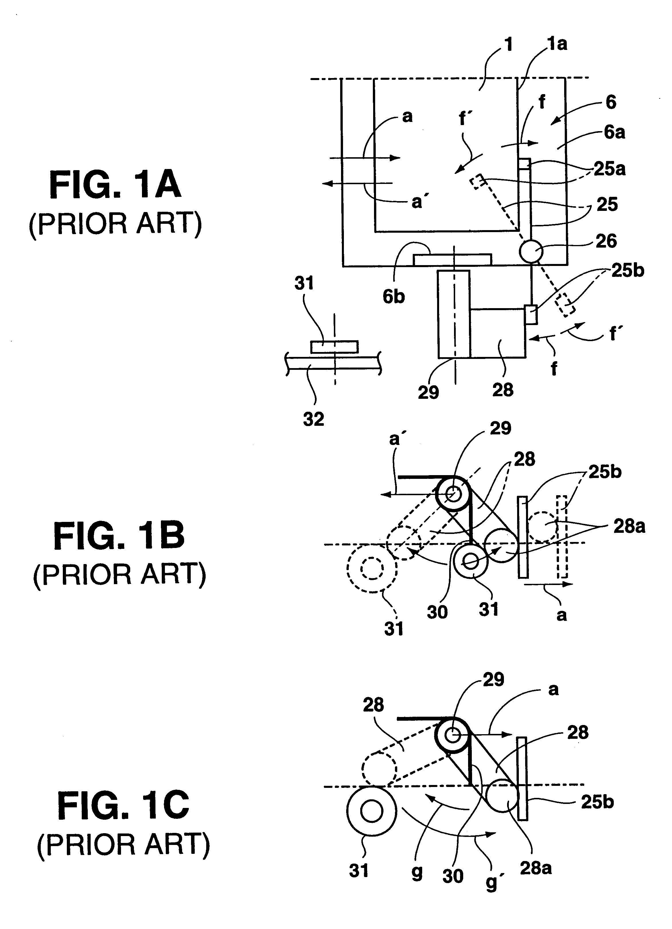
1. Field of the InventionThe present invention relates to a cassette type recording / reproducing apparatus for recording / reproducing information by using a tape cassette, such as a video cassette recorder or the like.2. Description of the Prior ArtThere has been known a conventional technique shown in FIGS. 1A to 1J, which is relating to a cassette type recording / reproducing apparatus such as a video recorder or the like. In the conventional technique shown in FIGS. 1A to 1C, a cassette discharge lever 25 is secured through a vertical supporting pin 26 to a bottom plate 6a of a cassette stage 6 so as to be freely rotatable in directions as indicated by arrows f,f' within a horizontal plane, and a cam driven lever 28 for rotationally driving the cassette discharge lever 25 is secured through a horizontal supporting pin 29 to a side plate 6b of a cassette stage 6 so as to be freely rotatable in directions as indicated by arrows g,g' within a vertical plane. The cam driven lever 28 is r...

Claims


Application Information

Patent Timeline
Patent Type & Authority Patents(United States)
IPC IPC(8): G11B33/02G11B25/00G11B25/06G11B15/675
CPCG11B15/67505G11B15/67515G11B33/027G11B15/67549G11B25/066G11B15/67547G11B15/67544G11B33/06G11B2220/90
Inventor SUZUKI, KATSUHIRO
Owner SONY CORP
Learn More