
Bi-centered drill bit having improved drilling stability mud hydraulics and resistance to cutter damage

a drill bit and drilling stability technology, applied in drill bits, earth drilling and mining, cutting machines, etc., can solve the problems of limited usefulness of underreamers, difficult control of the drilling direction of holes through earth formations, and unforeseen large lateral forces

Inactive Publication Date: 2001-08-07
SMITH INT INC
View PDF29 Cites 186 Cited by
  • Summary
  • Abstract
  • Description
  • Claims
  • Application Information

AI Technical Summary

Problems solved by technology

Mechanical difficulties with the extensible arms limited the usefulness of underreamers.
This turning moment can, among other things, make it difficult to control the drilling direction of the hole through the earth formations.
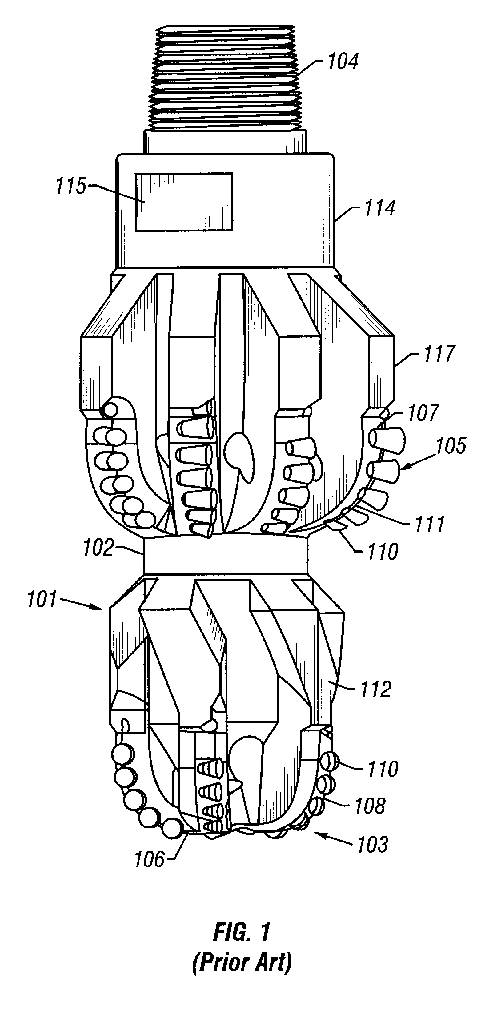
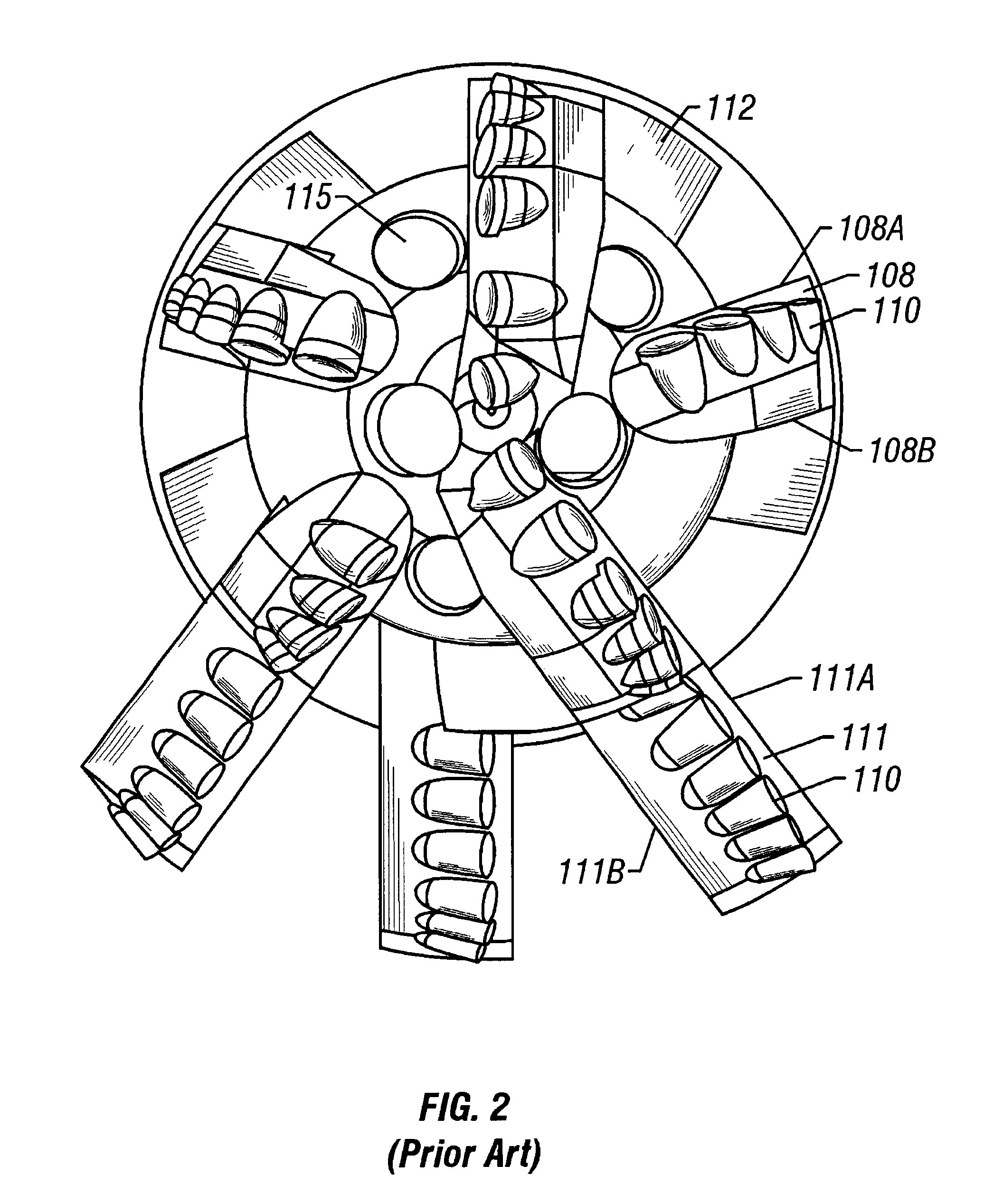
Still another limitation of prior art bi-centered bits is that the force balance is calculated by determining the net vector sum of forces on the reaming section 110, and designing the counterforce at the pilot section 106 to offset the net vector force on the reaming section without regard to the components of the net vector force originating from the individual PDC inserts.
Some bi-center bits designed according to methods known in the art can have unforeseen large lateral forces, reducing directional control and drilling stability.

Method used


Image

  • Bi-centered drill bit having improved drilling stability mud hydraulics and resistance to cutter damage
  • Bi-centered drill bit having improved drilling stability mud hydraulics and resistance to cutter damage
  • Bi-centered drill bit having improved drilling stability mud hydraulics and resistance to cutter damage

Examples


Embodiment Construction

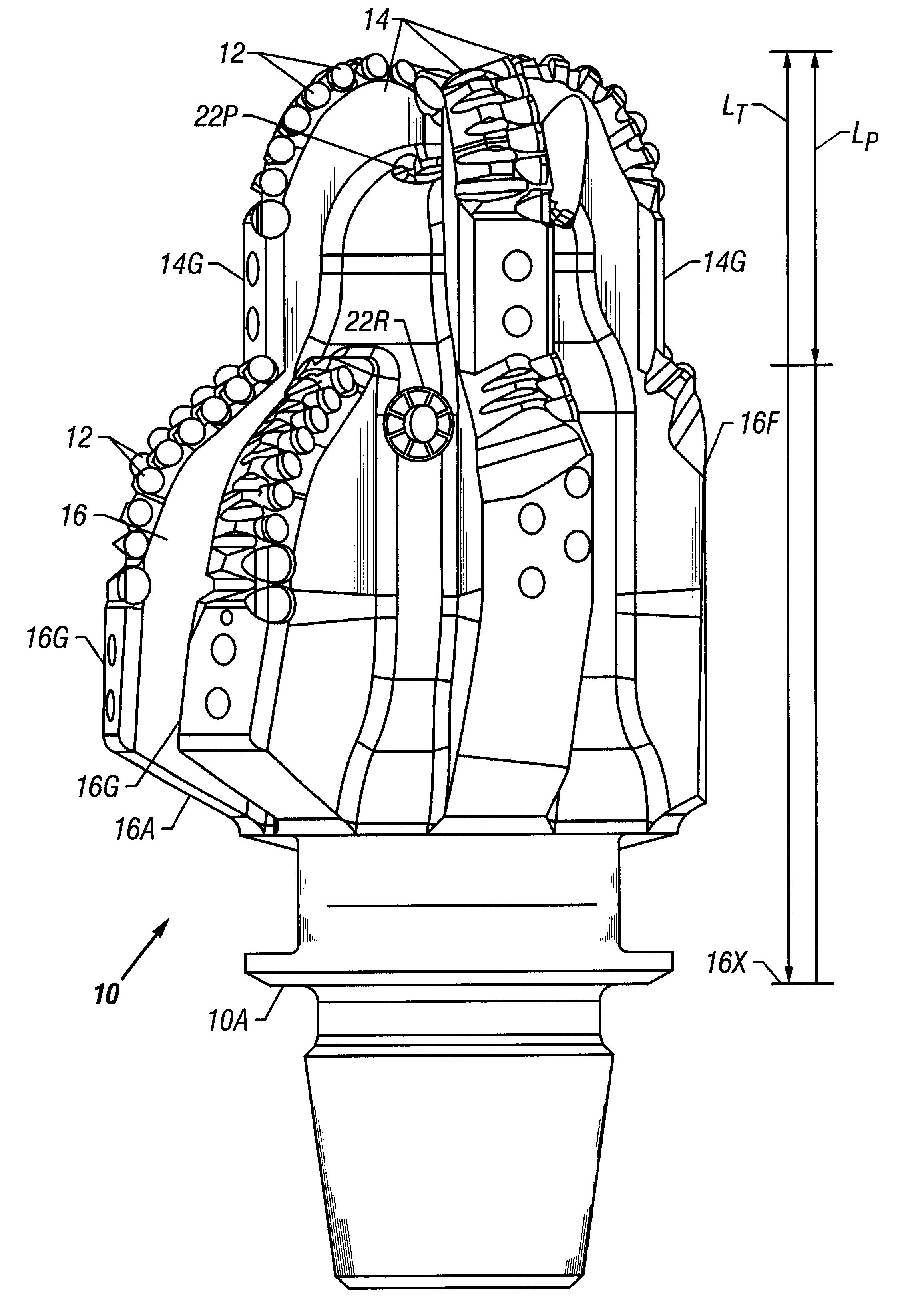
An example of a drill bit incorporating several aspects of the invention is shown in oblique view in FIG. 3. A bi-center drill bit 10 includes a body 18 which can be made from steel or other material conventionally used for drill bit bodies. One end of the body 18 can include thereon a threaded connection 20 for attaching the bit 10 to a source of rotary power, such as a rotary drilling rig (not shown) or hydraulic motor (not shown) so that the bit 10 can be turned to drill earth formations (not shown).

At the end of the body 18 opposite the threaded connection 20 is a pilot section 13 of the bit 10. The pilot section 13 can include a set of azimuthally spaced apart blades 14 affixed to or otherwise formed into the body 18. On each of the blades 14 is mounted a plurality of polycrystalline diamond compact (PDC) inserts, called cutters, such as shown at 12. The pilot blades 14 typically each extend laterally from the longitudinal axis 24 of the bit 10 by the same amount. The pilot sec...


PUM


Abstract

A bi-center drill bit includes pilot and reaming blades affixed to a body at azimuthally spaced locations. The blades have PDC cutters attached at selected positions. In one aspect, the pilot blades form a section having length along the bit axis less than about 80 percent of a diameter of the section. In another aspect, selected pilot blades and corresponding reaming blades are formed into single spiral structures. In another aspect, shapes and positions of the blades and inserts are selected so that lateral forces exerted by the reaming and the pilot sections are balanced as a single structure. Lateral forces are preferably balanced to within 10 percent of the total axial force on the bit. In another aspect, the center of mass of the bit is located less than about 2.5 percent of the diameter of the bit from the axis of rotation. In another aspect, jets are disposed in the reaming section oriented so that their axes are within about 30 degrees of normal to the axis of the bit. In another aspect, the reaming blades are shaped to conform to the radially least extensive, from the longitudinal axis, of a pass-through circle or a drill circle, so the cutters on the reaming blades drill at the drill diameter, without contact to the cutters on the reaming blades when the bit passes through an opening having about the pass-through diameter.

Description

1. Field of the InventionThis invention relates generally to the field of polycrystalline diamond compact (PDC) drilling bits. More specifically, this invention relates to PDC bits which drill a hole through earth formations where the drilled hole has a larger diameter than the "pass-through " diameter of the drill bit.2. Description of the Related ArtDrill bits which drill holes through earth formations where the hole has a larger diameter than the bit's pass-through diameter (the diameter of an opening through which the bit can freely pass) are known in the art. Early types of such bits included so-called "underreamers ", which were essentially a drill bit having an axially elongated body and extensible arms on the side of the body which reamed the wall of the hole after cutters on the end of the bit had drilled the earth formations. Mechanical difficulties with the extensible arms limited the usefulness of underreamers.More recently, so-called "bi-centered " drill bits have been ...

Claims


Application Information

Patent Timeline
IPC IPC(8): E21B10/26
CPCE21B10/26E21B10/265
Inventor BEATON, TIMOTHY P.TRUAX, DAVID
Owner SMITH INT INC
Learn More