Process for manufacturing resin-coated fibers composite and an application thereof

a technology of resin coating and fiber, which is applied in the direction of document inserters, coatings, printing, etc., can solve the problems of inefficient increase of the volume of the die or resin bath, difficult to be the same filament, and difficult to consider all the design parameters

Inactive Publication Date: 2001-08-07
SAMBARK LFT
View PDF7 Cites 75 Cited by
  • Summary
  • Abstract
  • Description
  • Claims
  • Application Information

AI Technical Summary

Problems solved by technology

Actually it is very difficult to be same the filaments lengths from die inlet to die outlet because the approximate equation is literally approximated comprising assumptions, and there are quite a few parameters in association with the shapes of the pins and their alignment.
It is very difficult to consider all the design parameters and to avoid the extreme breakage

Method used


Image

  • Process for manufacturing resin-coated fibers composite and an application thereof
  • Process for manufacturing resin-coated fibers composite and an application thereof
  • Process for manufacturing resin-coated fibers composite and an application thereof

Examples


Embodiment Construction

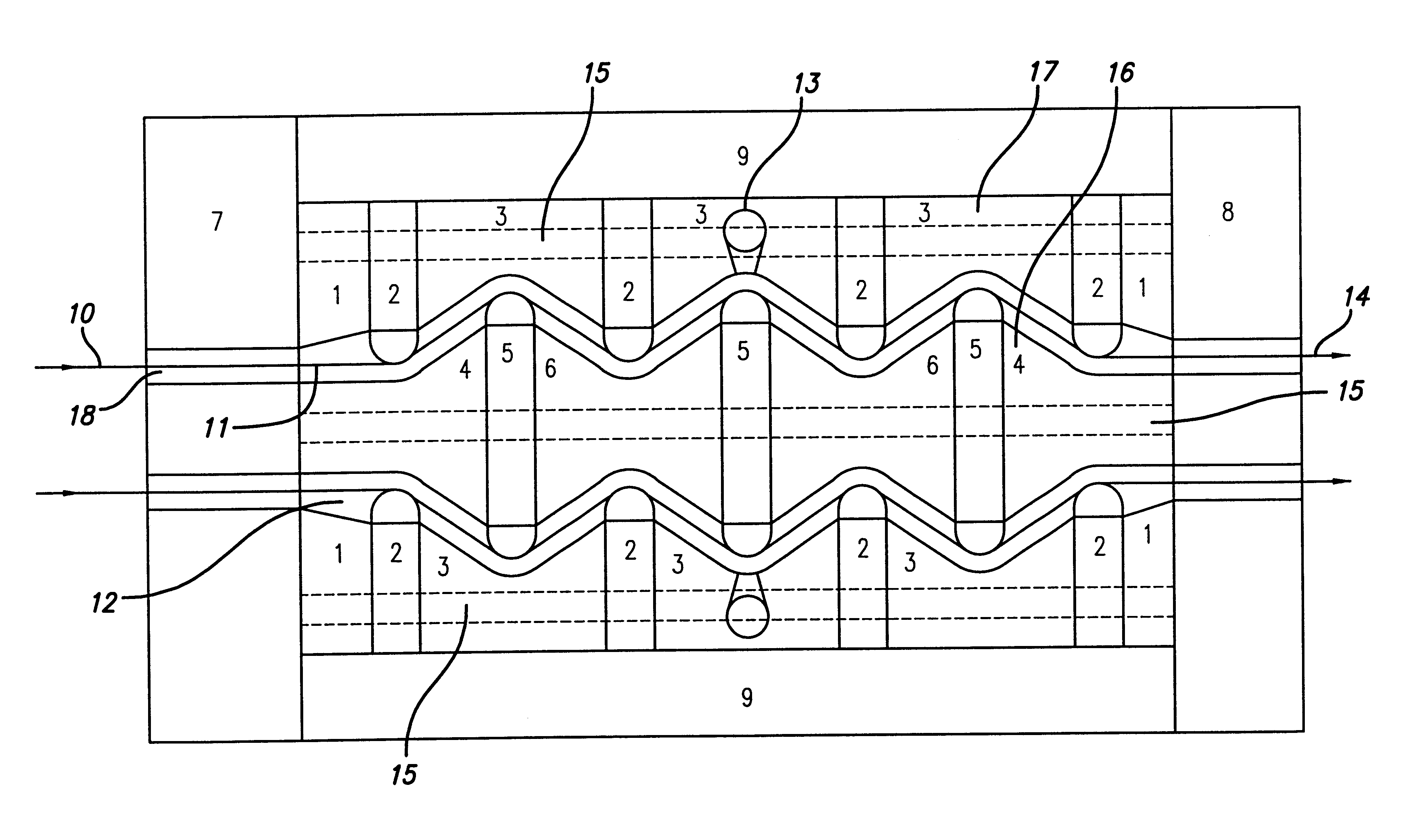
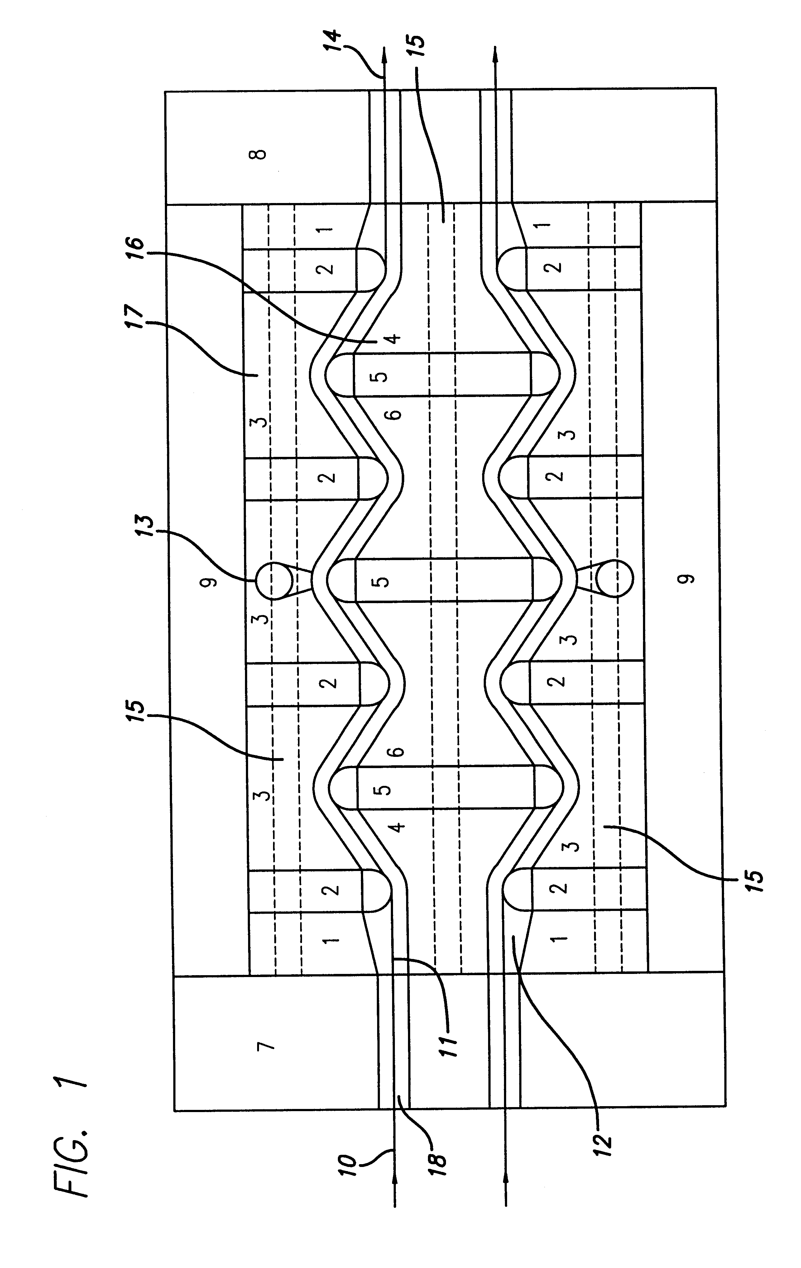
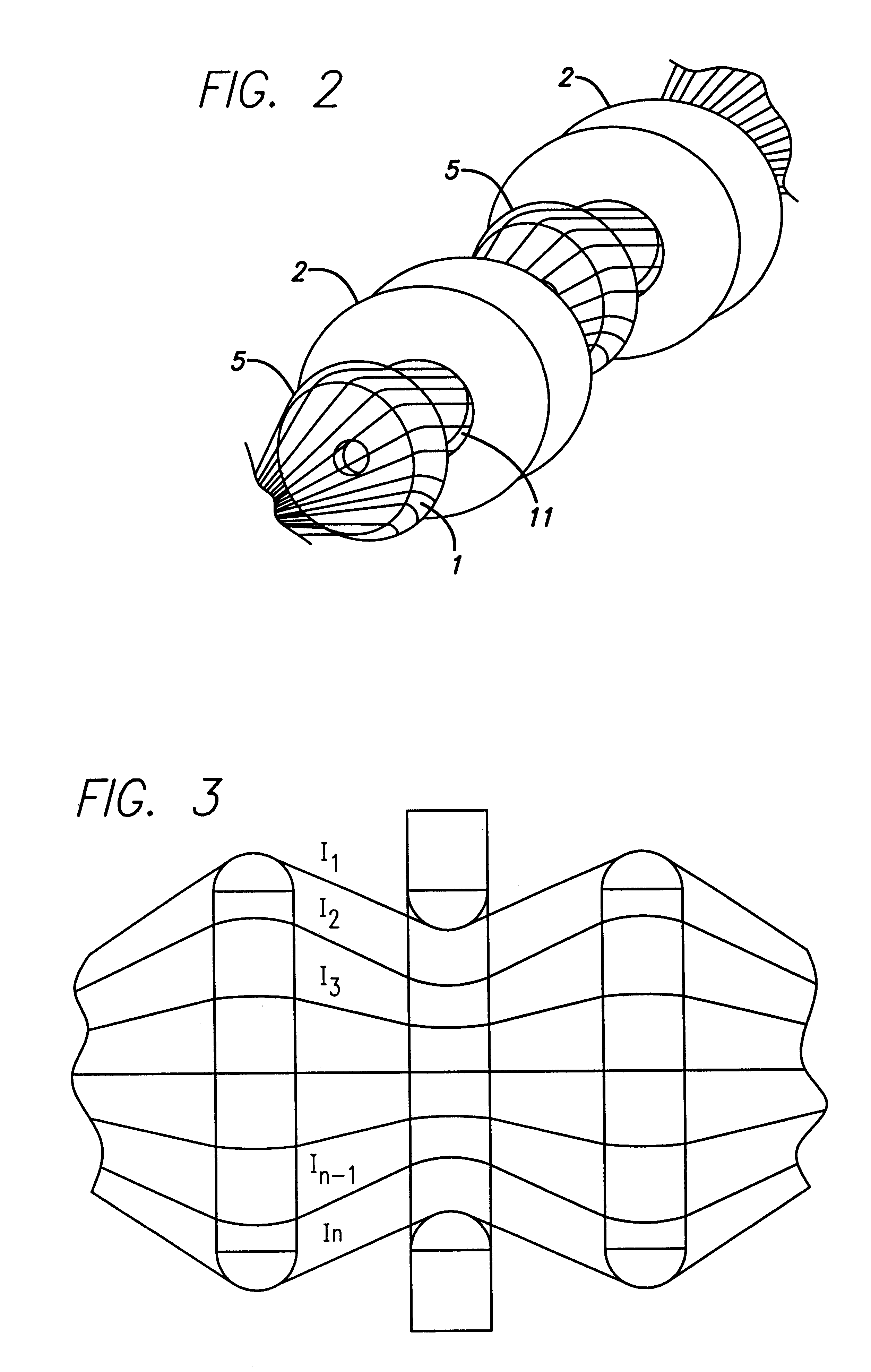
The present invention relates to an apparatus assembly for producing a resin coated fiber composite of a rod shape, tubular-shape or plate shape comprises a plurality of first members 2 having an annular shape with a semi-circular ring shaped internal surface, a plurality of second members 5 having a disc shape with a semi-circular ring shaped external surface, a plurality of first connectors 1, 3 for assembling the first members 2, a plurality of second connectors 4, 6 for assembling the second members 5, an outer die member 17 semi-assembled with the plurality of the first members 2 and the first connectors 1, 3, an inner die member 16 semi-assembled with the plurality of the second members 5 and the second connectors 4, 6, a heater 9 disposed outside of the outer die member 17, the heater 9 being a primary heat source for heating molten resin, an inlet nozzle 7 for inlaying fiber filament bundles, an outlet nozzle 8 for outlying fiber filament bundles, a zigzag shaped tunnel 18 f...


PUM

PropertyMeasurementUnit
Viscosityaaaaaaaaaa
Lengthaaaaaaaaaa
Lengthaaaaaaaaaa

Abstract

An apparatus for producing a resin coated fiber composite of a rod shape, tubular-shape or plate shape comprises a plurality of first members having an annular shape with a semi-circular ring shaped internal surface, second members having a disc shape with a semicircular ring shaped external surface, first connectors for assembling the first members, second connectors for assembling the second members, an outer die member semi-assembled with the first members and connectors, an inner die member semi-assembled with the second members and connectors, a heater, an inlet nozzle and an outlet nozzle, a zigzag shaped tunnel formed between the inner and outer die members for providing a narrow flow path of the fiber filaments, and resin inlet ports to fill the molten resin in the zigzag shaped tunnel and pressurize the flow path of the fiber filaments. A process for preparing a resin coated fiber composite of a rod-shape, tubular-shape or plate-shape comprises steps of spreading fiber filaments by passing the fiber filaments through a first member having a convex-concave portion to prevent fracture of the fiber filaments, and sequentially tensioning through a series of first and second members all along a narrow flow path to maximize molten resin penetrating surface area, impregnating pressurized molten resin into the fiber filaments continuously by passing the fiber filaments through a series of the first and second members all along the narrow flow path of a zigzag shaped tunnel to maximize molten resin penetrating time, and wherein pressurization of the molten resin maximizes penetration of molten resin into pores of the fiber filaments and minimizes possibility of resin degradation, stranding the resin-coated fiber filaments through a final set of the first members having the convex-concave portion for strengthening the fiber filaments, and integrating and pultruding the resin-coated fiber filaments continuously by passing the fiber filaments all along the narrow flow path of the zigzag shaped tunnel to form a desired diameter through the outlet nozzle.

Description

1. Field of the InventionThe present invention relates to an apparatus and an economical process for continuously coating fiber filaments by passing the fiber filaments through a molten resin closed die. More particularly, the present invention relates to an apparatus and an economical process for continuously coating the fiber filaments wherein each filament of a fiber bundle is coated continuously in a narrow flow path of a zigzag shaped tunnel formed between an inner die member and an outer die member along the fiber filaments moving direction.2. Description of Prior ArtFor the coating of a fiber bundle, the resin should be impregnated enough into a bed layer of the fiber bundle which is composed of quite a lot of fiber filaments while the fiber bundle stays in the resin of the die so that the fiber filaments may be drenched as much as possible.According to the theory, in order to satisfactorily obtain a well impregnated resin coated fiber bundle, it is required to increase the p...

Claims


Application Information

Patent Timeline
IPC IPC(8): B29B15/10B29B15/12B29C70/04B29C70/50D06B3/02
CPCB29C70/50B29B15/122D06B3/02
Inventor LEE, JAE-SHIKPARK, SOUN-HIEPARK, SOON-HOBAEK, DEOG-MAN
Owner SAMBARK LFT
Why Eureka
Try Eureka