Apparatus for deploying an underwater pipe string

a technology for underwater pipes and cables, applied in mechanical equipment, pipe laying and repair, pipe-laying vessels, etc., can solve the problems of inability to respond in real time, high cost of flexible pipes, and a large number of vertical towers

Inactive Publication Date: 2001-08-14
OIL STATES INDS UK
View PDF56 Cites 81 Cited by
  • Summary
  • Abstract
  • Description
  • Claims
  • Application Information

AI Technical Summary

Problems solved by technology

However, flexible pipe is very expensive, much more so than standard steel pipe.
This presented the practical problem of how to deploy a steel pipe string vertically from a starting point on the ocean floor to a hand-off and terminus at a floating production system; thereby leading to the development and use of J-Lay towers for this purpose.
Rigidly installed, vertical towers engender a number of problems caused by an inability to respond in real time to the dynamic forces encountered during pipe laying operations.
Other deficiencies include the fact that they do not allow: 1) control of the bending stress and tension within the pipe string as it is deployed in an arc to the sea bed; 2) the laying vessel to weather vane or rotate about the pipe and thereby prevent torsional wind-up of the pipe string; ...

Method used


Image

  • Apparatus for deploying an underwater pipe string
  • Apparatus for deploying an underwater pipe string
  • Apparatus for deploying an underwater pipe string

Examples


Embodiment Construction

Illustrative embodiments of the invention are described below. In the interest of clarity, not all features of an actual implementation are described in this specification. It will of course be appreciated that in the development of any such actual embodiment, numerous implementation-specific decisions must be made to achieve the developers' specific goals, such as compliance with system-related and business-related constraints, which will vary from one implementation to another. Moreover, it will be appreciated that such a development effort, even if complex and time-consuming, would be a routine undertaking for those of ordinary skill in the art having the benefit of this disclosure.

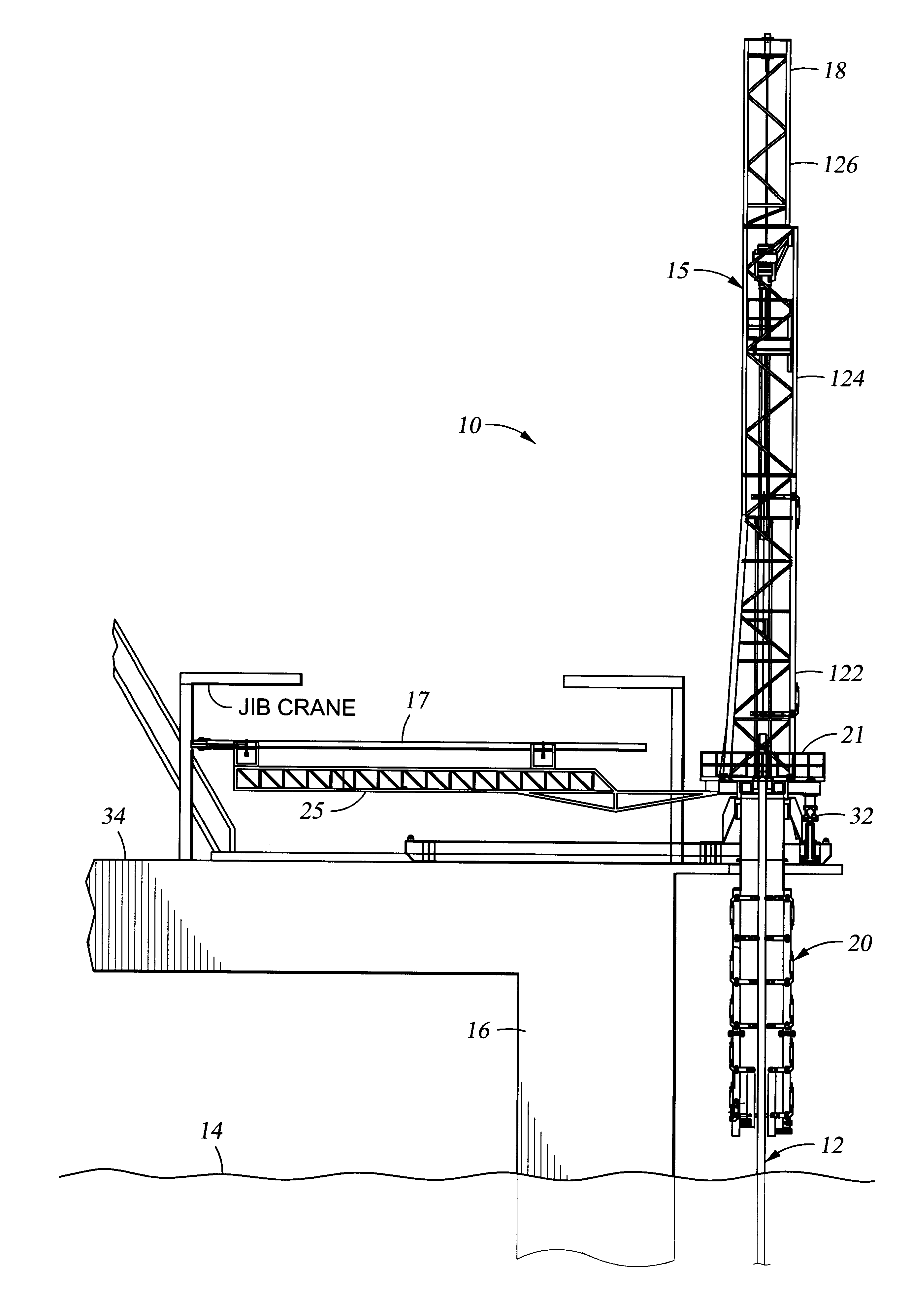
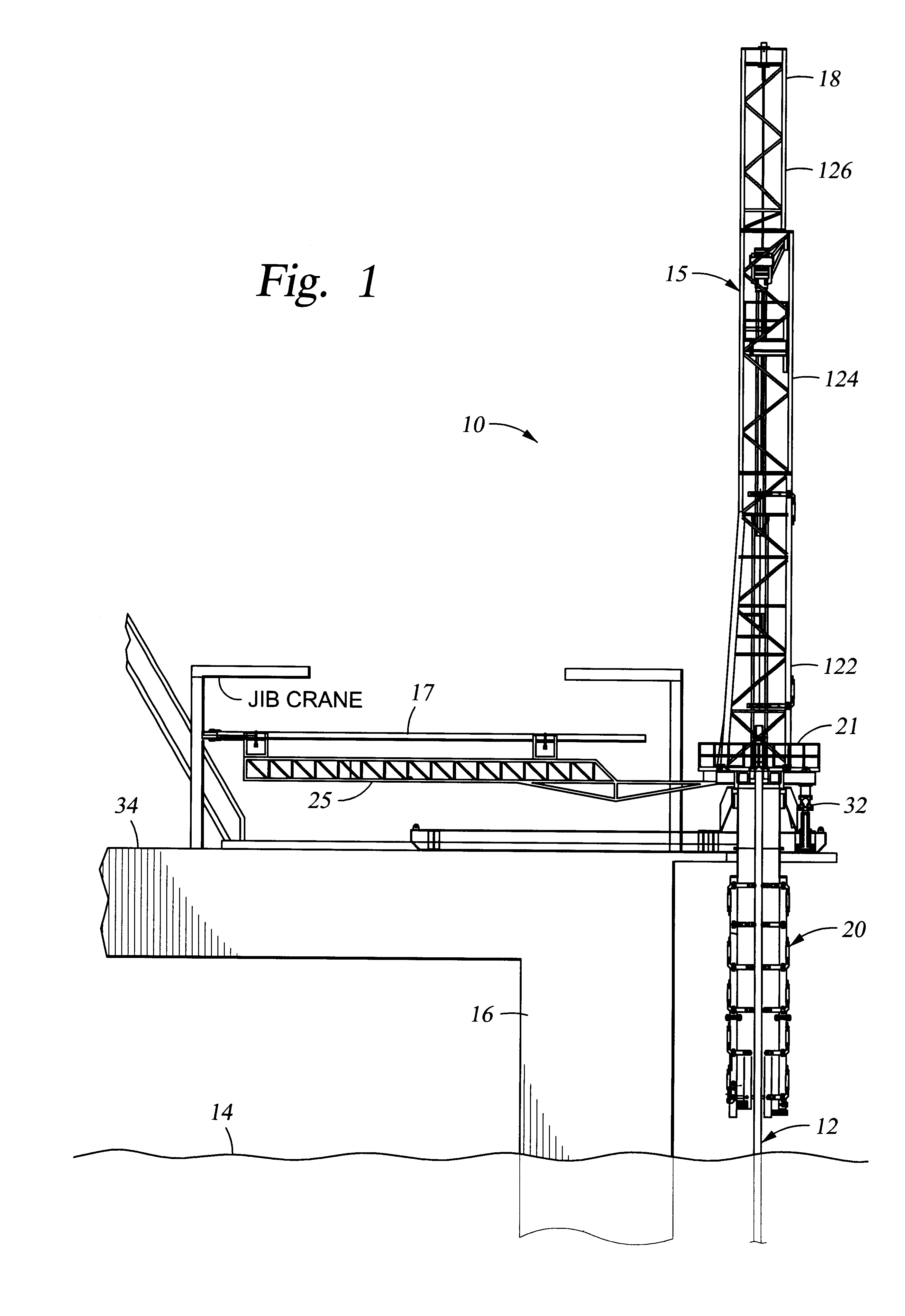
FIG. 1 illustrates an apparatus 10 as may be used in various embodiments to deploy a pipe string 12 beneath the surface of a body of water 14 from a vessel 16. Note that, although this disclosure is frequently in terms of subsea operations, it is to be understood that the invention is not limited to oc...


PUM


Abstract

An apparatus for deploying an underwater pipe string includes a mast, an articulated table, a stinger, and a pipe erector. The mast is affixed to the articulated table and extends above the articulated table. The stinger is affixed to the articulated table and depends below the articulated table. The pipe erector is connected to the mast for loading pipe joints up to the mast. A pipe joint loaded in the mast is welded to the pipe string, which depends from the articulated table and through the stinger toward a seabed. The stationary table is articulated for tilting of the table, the mast, and the stinger azimuthally and angularly for a preferred direction and lay angle of the pipe string being deployed.

Description

1. Field of the InventionThis invention relates generally to laying underwater pipe and, more particularly, to installing underwater pipelines on the seabed and / or connecting the same to floating terminals at the surface.2. Description of the Related ArtFloating production facilities require risers to provide fluid conduits between subsea equipment and the surface facility (or platform). The floating structure responds dynamically to the forces of the environment to which it is exposed. This means that the conduit connecting the structure and subsea equipment must be connected in a manner that accommodates relative motions. The conduit, of course, requires top and bottom interfaces to establish functional connections. At one time, flexible pipe was considered as the only feasible means of providing flowline connections from equipment on the sea bed to a floating production vessel. However, flexible pipe is very expensive, much more so than standard steel pipe. As a result, the use o...

Claims


Application Information

Patent Timeline
IPC IPC(8): F16L1/20F16L1/19F16L1/225F16L1/235F16L1/12
CPCF16L1/19F16L1/207B63B35/03F16L1/235F16L1/225
Inventor BAUGH, BENTON F.
Owner OIL STATES INDS UK
Why Eureka
Try Eureka