Cleanroom filter unit

a filter unit and cleaning room technology, applied in the field of cleaning room filter units, can solve the problems of inability to reliably glue the corner joints of the above described assemblage of the filter unit, inability inability to weld the separate wall elements together in order to provide leakproof corner joints, etc., to achieve the effect of reliable tightness, simple design and inexpensive production of the filter uni

Inactive Publication Date: 2001-08-14
ABB FLAEKT AB
View PDF14 Cites 4 Cited by
  • Summary
  • Abstract
  • Description
  • Claims
  • Application Information

AI Technical Summary

Benefits of technology

The object of the present invention is to provide a filter unit for cleanroom ceilings, which is reliably tight and has a simple design that enables an inexpensive production of the filter unit.

Problems solved by technology

A problem of this known design, however, is that the glued corner joints are not reliable.
Furthermore, the above described assemblage of a filter unit demands a great deal of work to carry out.
To weld the separate wall elements together in order to provide leakproof corner joints is not a good solution to the problem described above, because the heat generated during the welding operation would damage the heat sensitive filter, which is composed of glued fibreglass paper.

Method used


Image

  • Cleanroom filter unit
  • Cleanroom filter unit

Examples


Embodiment Construction

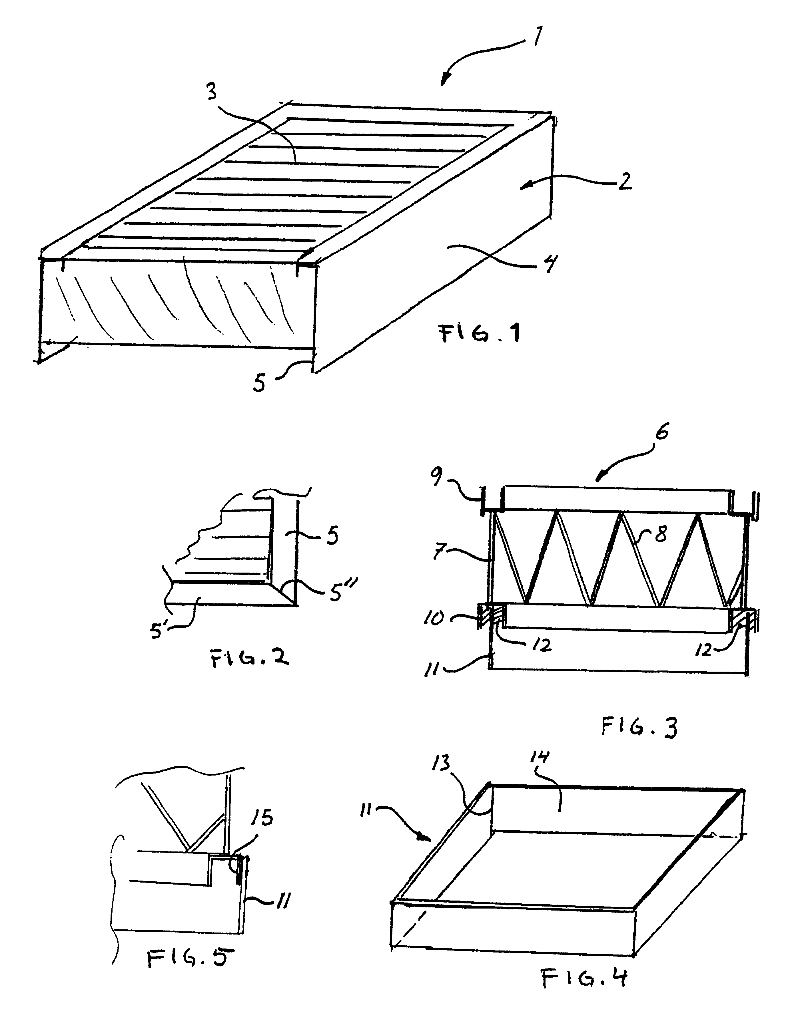
In FIG. 1 there is shown a schematic perspective view of a known HEPA-filter unit 1 with a wall 2 surrounding a filter 3. The wall 2 comprises smooth aluminum wall portions 4 with downwardly directed wall extensions forming a sealing knife 5.

As shown in FIG. 2 adjacent wall extensions 5, 5' of the sealing knife are glued together to achieve airtightness. The lateral extension of the glue surface 5" where the adjacent wall extensions 5,5' abut each other will be in the order of 1.5 mm, while the height of the sealant knife may amount to at least 50 mm. As a consequence, the risk of leakage will be considerable and therefore this design is not suitable for use in cleanroom facilities having strict demands of cleanliness.

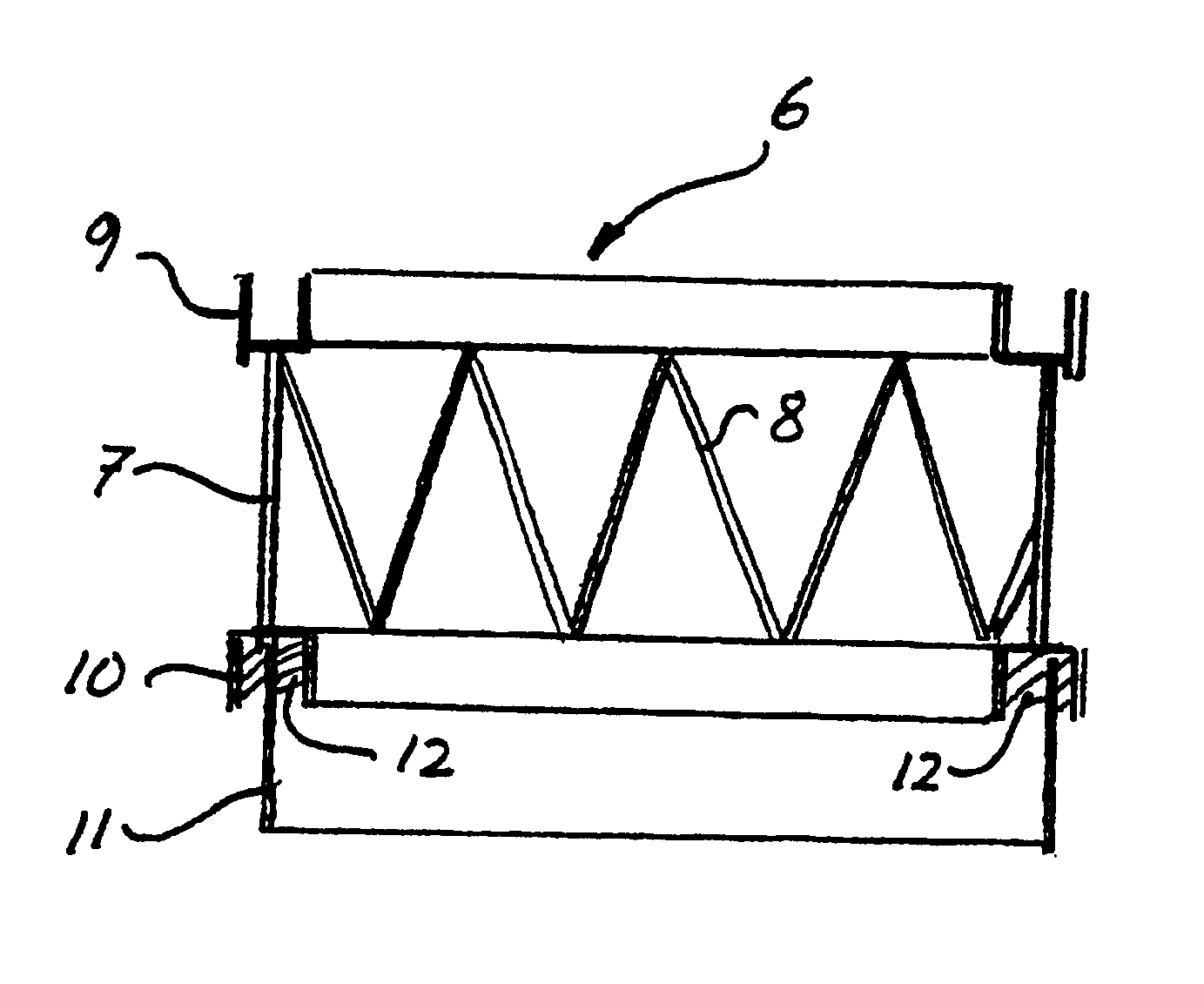
In FIG. 3 there is shown a cross-sectional view of a filter unit 6 according to a preferred embodiment of the invention. The filter unit 6 comprises a circumferential wall composed of four vertical interconnected wall portions 7 taking the shape of a rectangular box, i...


PUM

PropertyMeasurementUnit
thicknessaaaaaaaaaa
heightaaaaaaaaaa
heightaaaaaaaaaa

Abstract

A filter unit for airtight attachment to a framework of a cleanroom ceiling includes a filter, a circumferential wall surrounding the filter, and a downwardly projecting sealing knife to be received in a sealant containing groove formed in said framework. The sealing knife includes vertical weldable wall elements interconnected by welding and mounted on the circumferential wall by airtight mounting means.

Description

FIELD OF THE INVENTIONThe present invention relates to a cleanroom filter unit for airtight attachment to a framework of a cleanroom ceiling, comprising a filter, a vertical circumferential wall surrounding the filter and having a lower edge, and a sealing knife projecting downwardly from the lower edge of the circumferential wall to be received in a sealant containing groove formed in the framework of the cleanroom ceiling.DESCRIPTION OF THE RELATED ARTIn prior cleanroom applications air is generally supplied through so called HEPA-filters arranged in the framework of the cleanroom ceiling. In this connection it is essential that no leakage occurs between the filter and the framework.Traditional filter units are fabricated by gluing together separate straight wall portions to form the circumferential wall surrounding the filter so that the final filter unit takes the shape of a rectangular box with glued corner joints. The sealing knife comprises vertical extensions of said straigh...

Claims


Application Information

Patent Timeline
Patent Type & Authority Patents(United States)
IPC IPC(8): B01D46/24F24F3/16B01D46/00F24F7/06B01D46/10B01D46/52
CPCB01D46/10B01D46/521F24F3/161B01D2265/04Y10S55/31B01D2279/51B01D2271/02F24F3/167
Inventor LARSSON, BERTIL
Owner ABB FLAEKT AB
Why Eureka
Try Eureka