
Working robot for heat exchangers and method of operating said working robot

a technology of working robot and heat exchanger, which is applied in the direction of furniture, programme control, instruments, etc., can solve the problems of increasing the time required for assembling and disassembling the robot in the water chamber, and affecting the operation efficiency of the robo

Inactive Publication Date: 2001-08-21
UNIVERSAL SHIPBUILDING CORP
View PDF12 Cites 27 Cited by
  • Summary
  • Abstract
  • Description
  • Claims
  • Application Information

AI Technical Summary

Benefits of technology

According to the invention as described in Claim 2, when at least three combined-use arms are positioned by being fixedly connected to narrow tubes by the positioning mechanisms, a narrow tube inspecting operation is performed by the working devices. Further, in that the combined-use arms are simultaneously extended or contracted, the robot body is moved, and with three combined-use arms fixed, the working device of the remaining combined-use arm can be moved from a treated narrow tube to the next narrow tube. Therefore, as compared with a conventional working robot in which the movement mechanism of the robot body is separated from the working mechanism for probe insertion inspection and the like, the number of members can be reduced. Further, in that the combined-use arms are retracted toward the robot body, the robot can be made compact. This makes it possible to facilitate carrying into and out of a water chamber, to reduce the number of preparatory operations such as assembling and disassembling and to reduce the operating time.
According to the arrangement as described in Claim 20, the same effects as in Claim 18 can be attained by setting the working reference position of the robot at a position closest to the tube sheet and setting the stroke of each push-in driving device for closer approach to the tube sheet.

Problems solved by technology

Therefore, there has been a problem that the operating time required for assembling and disassembling the robot in the water chamber and carrying it in and out increases.
According to the arrangement as described in Claim 19, when the connecting and fixing tool is extracted from the narrow tube, it sometimes happens that the portion of the robot body associated with this combined-use arm is moved further away from the tube sheet as a reaction so that the push-in nozzle no longer approaches the next narrow tube in the position where it is opposed to said narrow tube, making it difficult to insert a cleaning tool or the connecting and fixing tool.

Method used


Image

  • Working robot for heat exchangers and method of operating said working robot
  • Working robot for heat exchangers and method of operating said working robot
  • Working robot for heat exchangers and method of operating said working robot

Examples


Embodiment Construction

The invention will now be described in more detail with reference to the attached drawings.

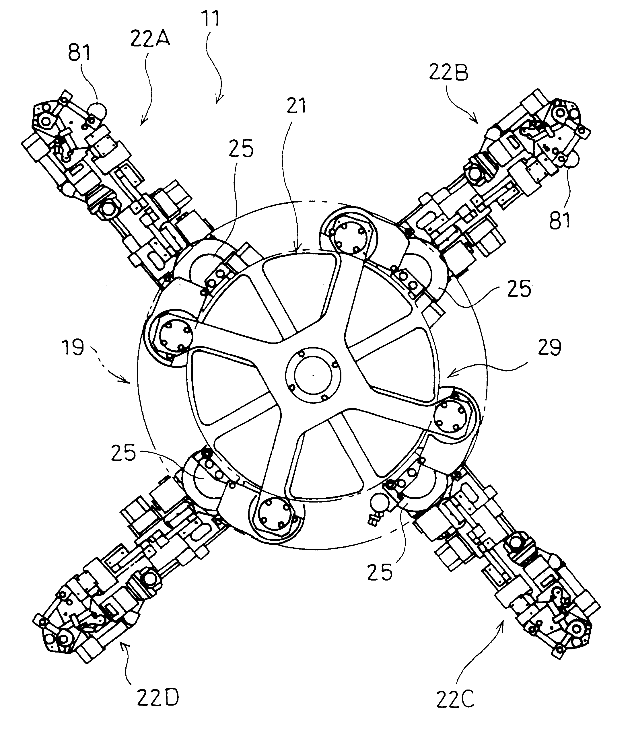
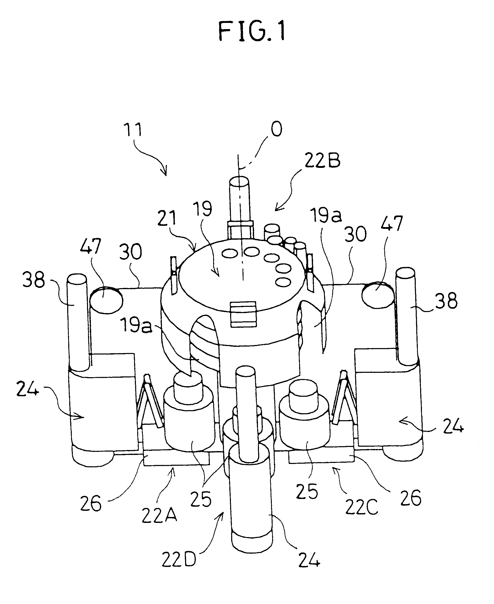
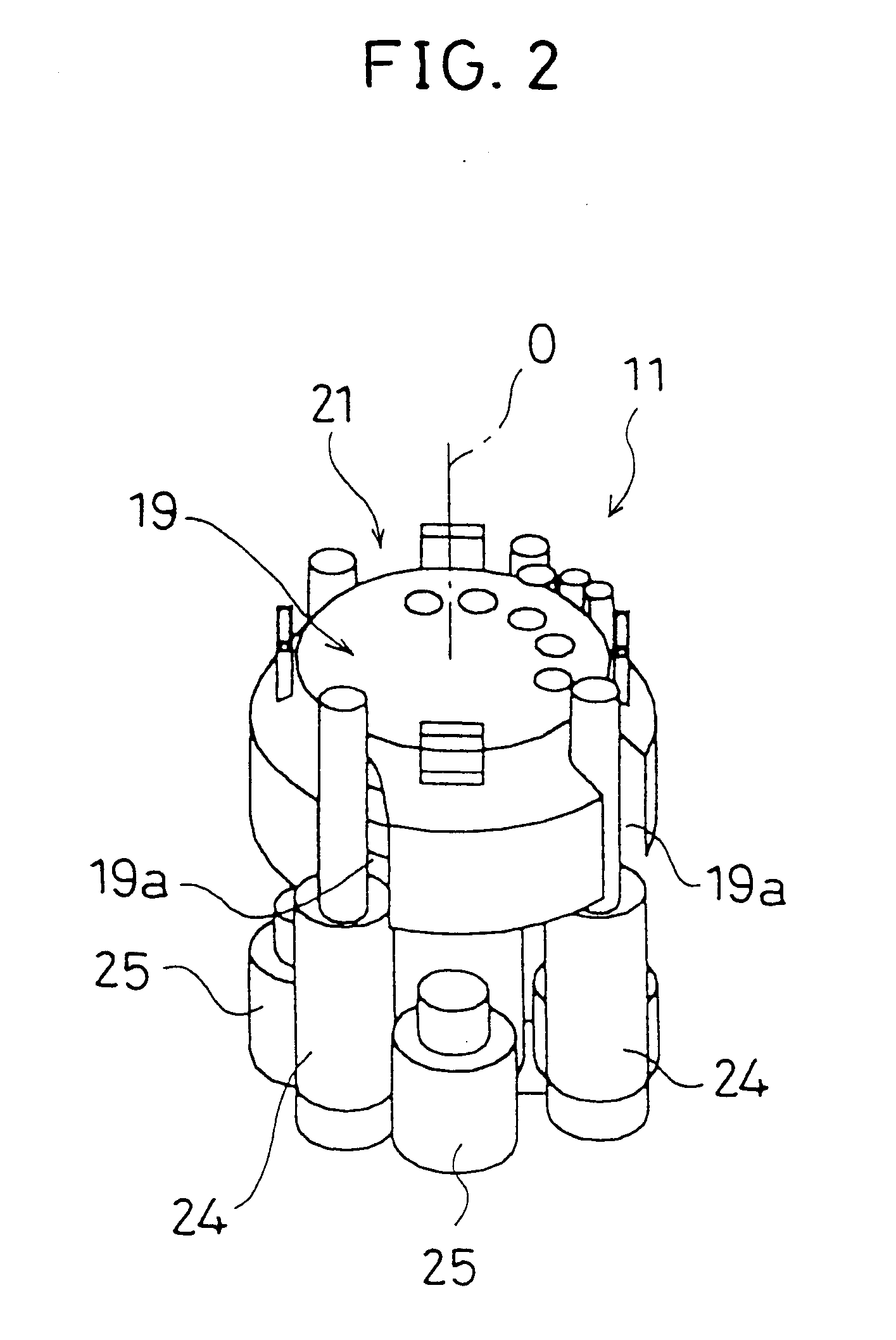
In FIGS. 1 through 5, a condenser 1 installed for example in a power station or the like has a number of narrow tubes 3 extending from one water chamber 2A to the other water chamber 2B to allow cooling water to flow therethrough, as shown in FIGS. 3 and 4. Since seawater is normally used as the cooling water for this condenser 1, it is necessary to regularly clean the narrow tubes 3 and inspect for damage such as cracks. A cleaning and inspecting robot (hereinafter referred to simply as the robot) 11 is used to clean and inspect these narrow tubes 3 and is so arranged that while self-advancing along a tube sheet 4 through which said many narrow tubes 3 open, the robot inserts a cleaning brush 12, which is a cleaning tool, into a narrow tube 3 and moves the brush 12 by cleaning water, which is a pressurized fluid, to clean the narrow tube 3. Further, a flaw detection probe 13, which is an insp...


PUM


Abstract

A robot body (21) is carried into the water chamber (2A) of a condenser (1) and disposed on a tube sheet (4) through which a number of narrow tubes (3) open. Inner nozzles (23) are inserted into narrow tubes (3) from working devices (24) installed on the front ends of four combined-use arms (22A through 22D) to position and fix the robot body (21). And the arm turning motors (25) and arm extending and contracting cylinder devices (26) of the combined-use arms (22A through 22D) are driven to move the robot body (21). Further, a cleaning brush (12) and a flaw detection probe (13) are inserted into a narrow tube (3) from each working device (24) and moved along the narrow tube (3) by cleaning water, whereby cleaning and inspection are performed. With three of the combined-use arms (22A through 22D) fixed to the narrow tubes (3), the inner nozzle (23) is extracted from the narrow tube (3) and the working device is moved to the next narrow tube (3).

Description

The present invention relates to a working robot for heat exchangers, adapted to effect cleaning or flaw detection test on the many water tubes of a condenser or a heat exchanger which water tubes are connected between and open through the tube sheets of two water chambers, and it also relates to a method of operating said working robot.TECHNICAL BACKGROUNDAs for known working devices for condensers, one is suggested in Japanese Patent Unexamined Publication Heisei 7-229695, which comprises guide rails extending along the surface of the tube sheet in the water chamber, and a working robot adapted to move while being guided along said guide rails. Another is suggested in Japanese Patent Unexamined Laid-open Applications No. 51-10201 and No. 3-199802, in which a robot body having a plurality of legs inserted in the openings in narrow tubes is provided with a working arm, said robot being moved along the tube sheet.In this connection, although manholes formed in the water chambers of c...

Claims


Application Information

Patent Timeline
Patent Type & Authority Patents(United States)
IPC IPC(8): B08B9/02B08B9/04B25J11/00F28G1/16F28G15/00F28G15/04F28G15/02F28G1/00F28G1/02B62D57/02
CPCB08B9/055B08B9/0551B08B9/0553B25J11/00F28G1/02F28G1/163F28G15/02F28G15/04B62D57/02Y10S700/90
Inventor IWASAKI, HISASHIKOMADA, SHUJITAKAHASHI, HIROTAKAHYUGA, MINORUFUJIMURA, TAKASHI
Owner UNIVERSAL SHIPBUILDING CORP
Features
  • Generate Ideas
  • Intellectual Property
  • Life Sciences
  • Materials
  • Tech Scout
  • Unparalleled Data Quality
  • Higher Quality Content
  • 60% Fewer Hallucinations
Learn More