Protection aid for protecting the hands and wrists of sketers

Inactive Publication Date: 2001-08-28
AHLBAUMER GEORG
View PDF2 Cites 27 Cited by
  • Summary
  • Abstract
  • Description
  • Claims
  • Application Information

AI Technical Summary

Problems solved by technology

Dangers associated with a hyperextension of the hand with respect to the forearm in the course of a fall on the ground are not considered in the U.S. patent and the protective device is not capable of protecting against such hyperextension

Method used


Image

  • Protection aid for protecting the hands and wrists of sketers
  • Protection aid for protecting the hands and wrists of sketers
  • Protection aid for protecting the hands and wrists of sketers

Examples


first embodiment

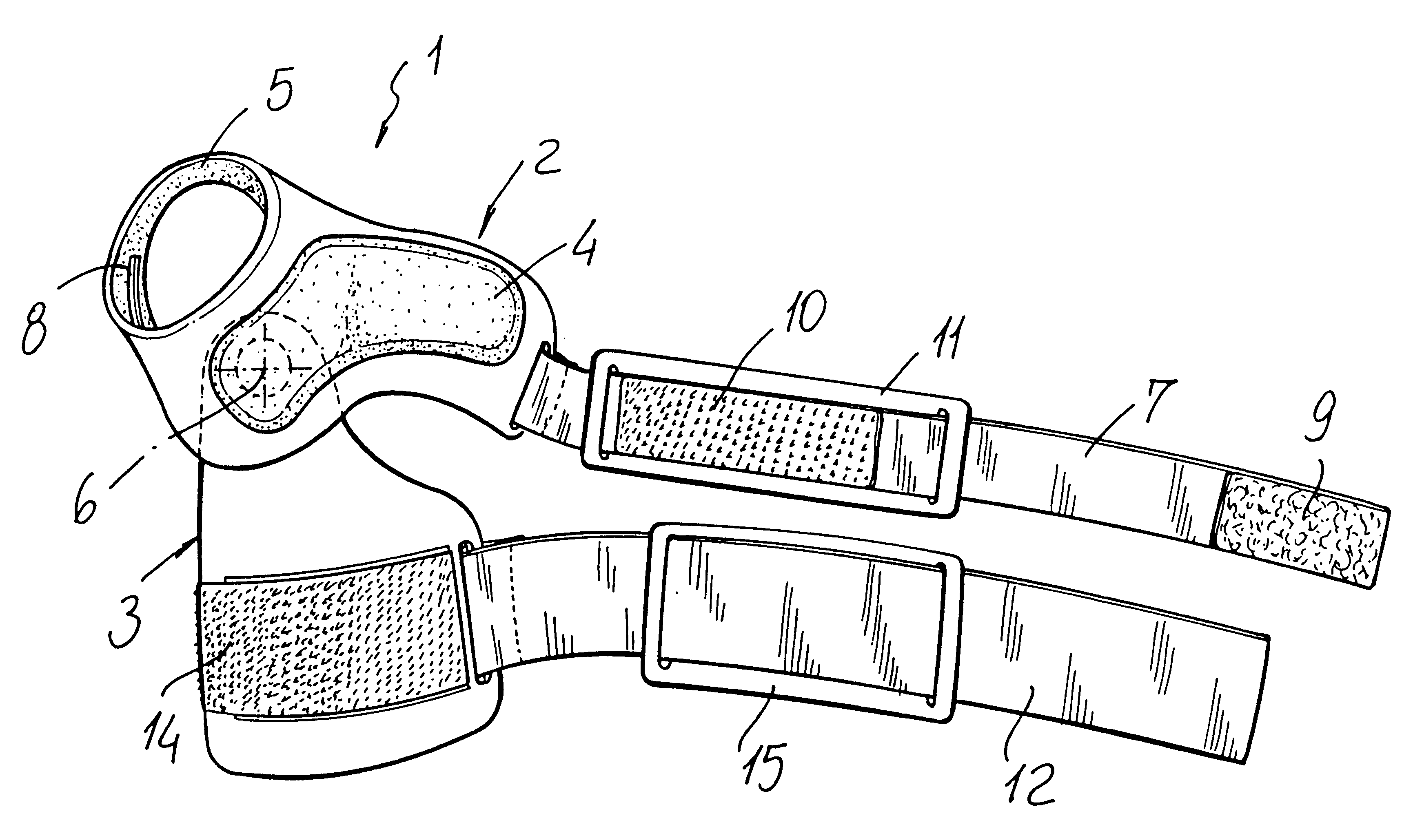
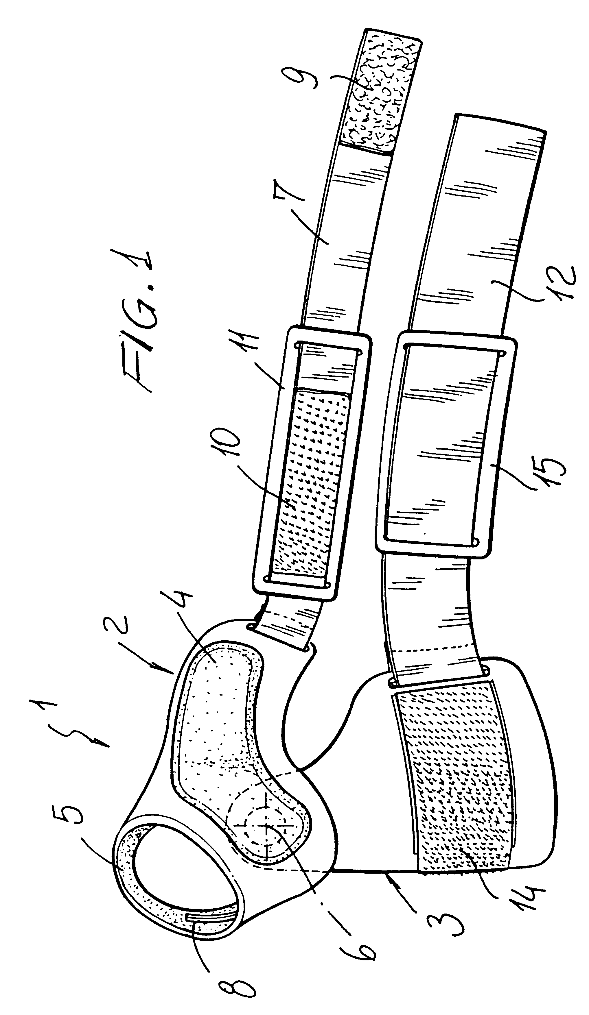
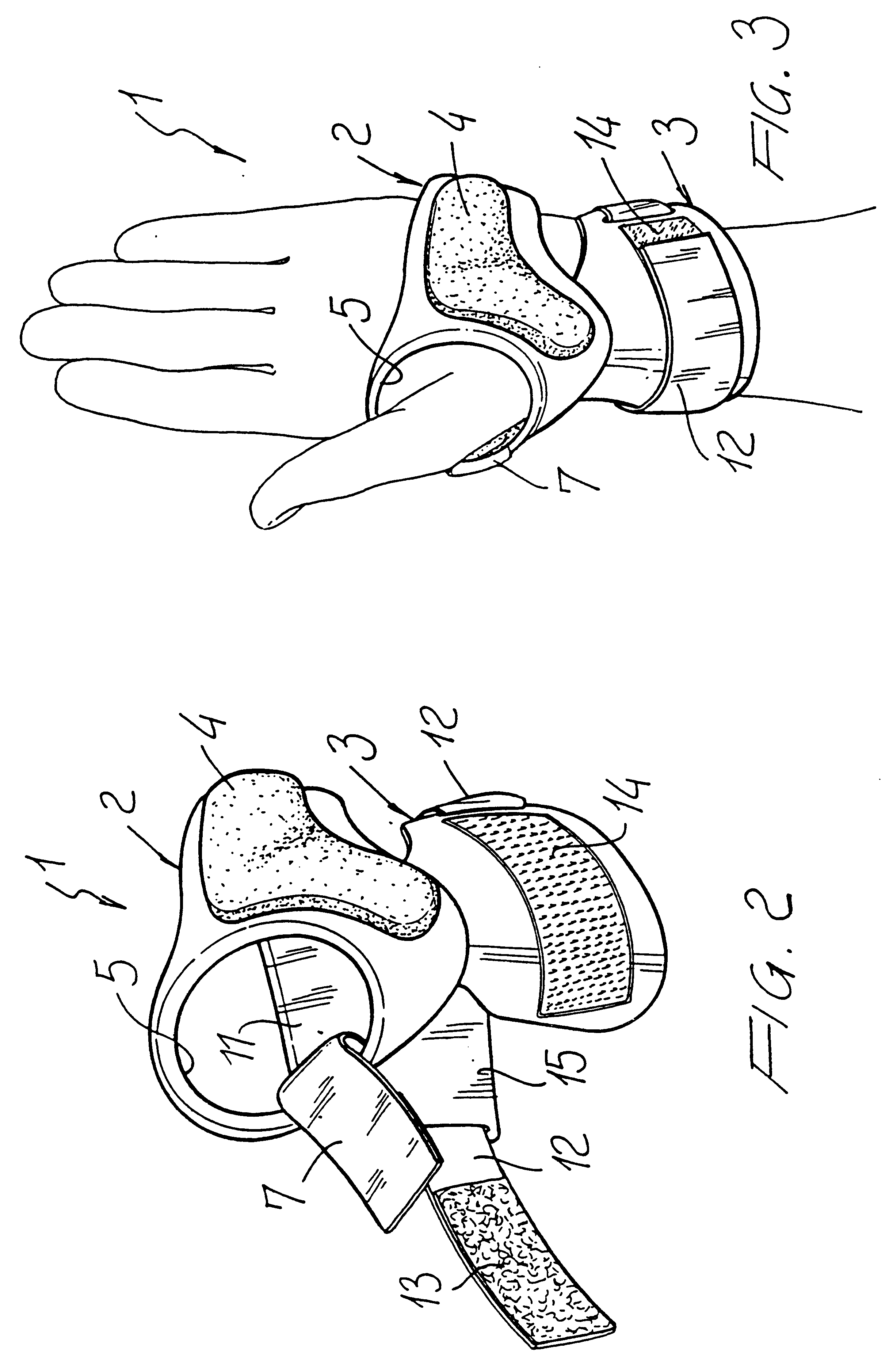
With reference to the number references of the above mentioned FIGS. 1 to 3, the protective aid according to the present invention, which has been generally indicated by the reference number 1, comprises a first shell-like protective plate 2, which is provided for being arranged on that region of the hand palm arranged near the wrist, and a second shell-like protective plate 3 to be arranged on the inside portion of the wrist.

The first protective plate 2, which is so designed as to assure a proper covering of that region of the hand palm arranged near the wrist articulation, i.e. that region which, in the case of a falling, is instinctively abutted against the ground, is provided, on the opposite face thereof, with respect to the hand, with a contoured reinforcement element 4 having shock-absorption properties and preferably being made from hard plastics. Its contoured outside surface serves as a friction surface for frictional engagement with ground and provides a gradual decelarat...

second embodiment

FIG. 4, is distinguished from the first embodiment in that the first protective element formed by the protective aid 2a and the abutment 4a is connected at the abutment element 4a with the second protective element formed by the protective plate 3a by means of an articulation 6a in the form of a rivet passing through corresponding through holes of the abutment element 4a and the protective plate 3a. The abutment element 4a, which is basically shaped like the abutment element 4 of FIG. 1 and is made also from hard plastics, has a recess 18a for the outer rivet head so that the outer rivet head of the articulation 6a is located below the friction surface (outer surface) of the abutment element and, accordingly, will not be engaged by ground during a frictional movement of the abutment element along ground.

Also the second protective plate or shell 3a is shaped like the protective plate 3 of FIG. 1 and made from hard plastics. The first protective plate 2a, which also can be denoted as ...

third embodiment

The third embodiment shown in FIG. 5 corresponds basically to the first embodiment of FIGS. 1, 2 and 3. The only difference is that the ring portion 5b is formed with a softer (softer than the rest of the first protective plate 2b) band to be arranged around the thumb and being riveted at its two ends to the protective plate 2b. This band 20b provides for more comfort, in particular, with respect to pressure points between the thumb and the forefinger. If the transmission of tension forces between the hand and the wrist or forearm is desired, a reinforcement wire or the like may be embedded within the band 20b, which wire is anchored at the protective plate 2b possibly by means of the two rivets connecting the band 20b with the protective plate 2b.

FIG. 6 shows a modification of the second embodiment shown in FIG. 4. In the fourth embodiment of FIG. 6, the abutment element 4c and the second protective plate 3c are directly connected without any articulation or the like. The connectin...


PUM


Abstract

The present invention relates to a protective aid for protecting the hands and wrists of skaters, which comprises a first protective element to be arranged on that region of the hand palm situated near the wrist. The protective aid comprises moreover a second protective element which can be arranged on the inside portion of the wrist and which is connected to the first protective plate via a connecting element. The protective aid is provided with engagement means for engaging the hand and/or wrist of the user, in order to firmly connect the protective aid to the user's hand, during use.

Description

The present invention relates to a protective aid for protecting the hands and wrists of skaters.As is known, a lot of persons, in particular young people, practise skating sprots, both at an agonistic level and at a hobby level, mainly due to the fact that are easily available on the market new types of skates comprising four aligned skating wheels.In particular, these new types of skates allow the skater to easily control his / her skate while greatly facilitating directional changes.On the other hand, the learning of a proper use of these skates is very difficult and requires a great perseverance by an inexperienced skater.Moreover, in practicing this sport, particularly at the start thereof, the skater is frequently subjected to dangerous failings because of a frequently occurring equilibrium loss.During these falls, the skater tends instinctively to limit possible damages by abutting against ground that portion of his / er hand palm arranged near the wrist, both in a case of a fron...

Claims


Application Information

Patent Timeline
IPC IPC(8): A41D13/08A41D13/05
CPCA41D13/088A41D13/082
Inventor AHLBAUMER, GEORGMICHELONI, VALTERGIUGNI, FABRIZIO
Owner AHLBAUMER GEORG
Why Eureka
Try Eureka