Air cylinder with cushion mechanism

a cushion mechanism and air cylinder technology, applied in the direction of functional valve types, servomotors, transportation and packaging, etc., can solve the problem of inability to adjust and achieve the effect of increasing the length of the cylinder invariably

Inactive Publication Date: 2001-08-28
SMC CORP
View PDF7 Cites 17 Cited by
  • Summary
  • Abstract
  • Description
  • Claims
  • Application Information

AI Technical Summary

Benefits of technology

It is another technical problem to be solved by the present invention to provide an air cylinder with a cushion mechanism which is simple and rationally designed as well in construction, having only means for restraining discharging air flow in the cylinder tube side and plural numbers of packing for piston-packing and cushion-packing in common disposed in the piston.
The above-described air cylinder with a cushion mechanism is not needed to form a long cushion ring and a long empty room for inserting the cushion ring, so that the longitudinal length of the cylinder can be reduced to that extent, resulting in enabling the air cylinder to be miniaturized.
Moreover, since the speed-regulating means for restraining the discharging air flow is disposed in the cylinder tube side and plural packing rings substantially serving the function as piston packing and cushioning packing in common are formed in the piston side, the designed structure thereof can be simplified by reducing the number of parts and rationalized as well to thereby reduce the manufacturing cost of the air cylinder.

Problems solved by technology

However, in the above-described conventional air cylinder with a cushion mechanism, since it is needed for the structural reason of the cushion mechanism that a required length of the cushion ring be disposed in at least one side of the piston and a long empty room for inserting the cushion ring be disposed in the cylinder tube, a problem that the longitudinal length of the cylinder is inevitably increased is indicated.

Method used


Image

  • Air cylinder with cushion mechanism
  • Air cylinder with cushion mechanism
  • Air cylinder with cushion mechanism

Examples


first embodiment

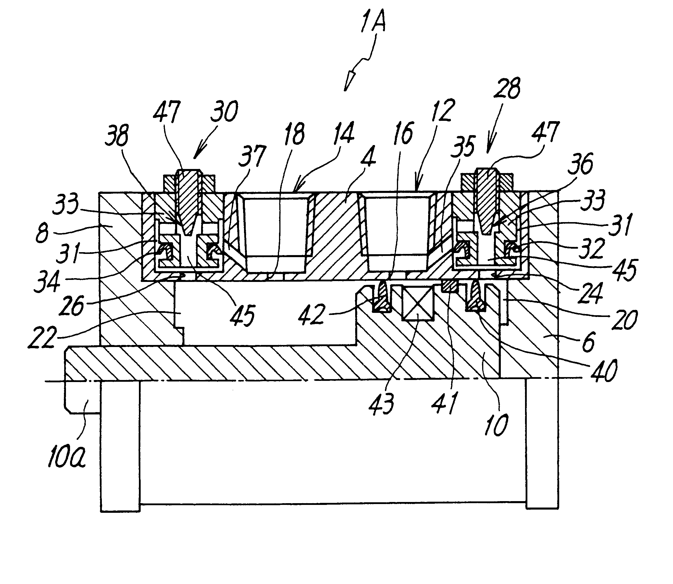
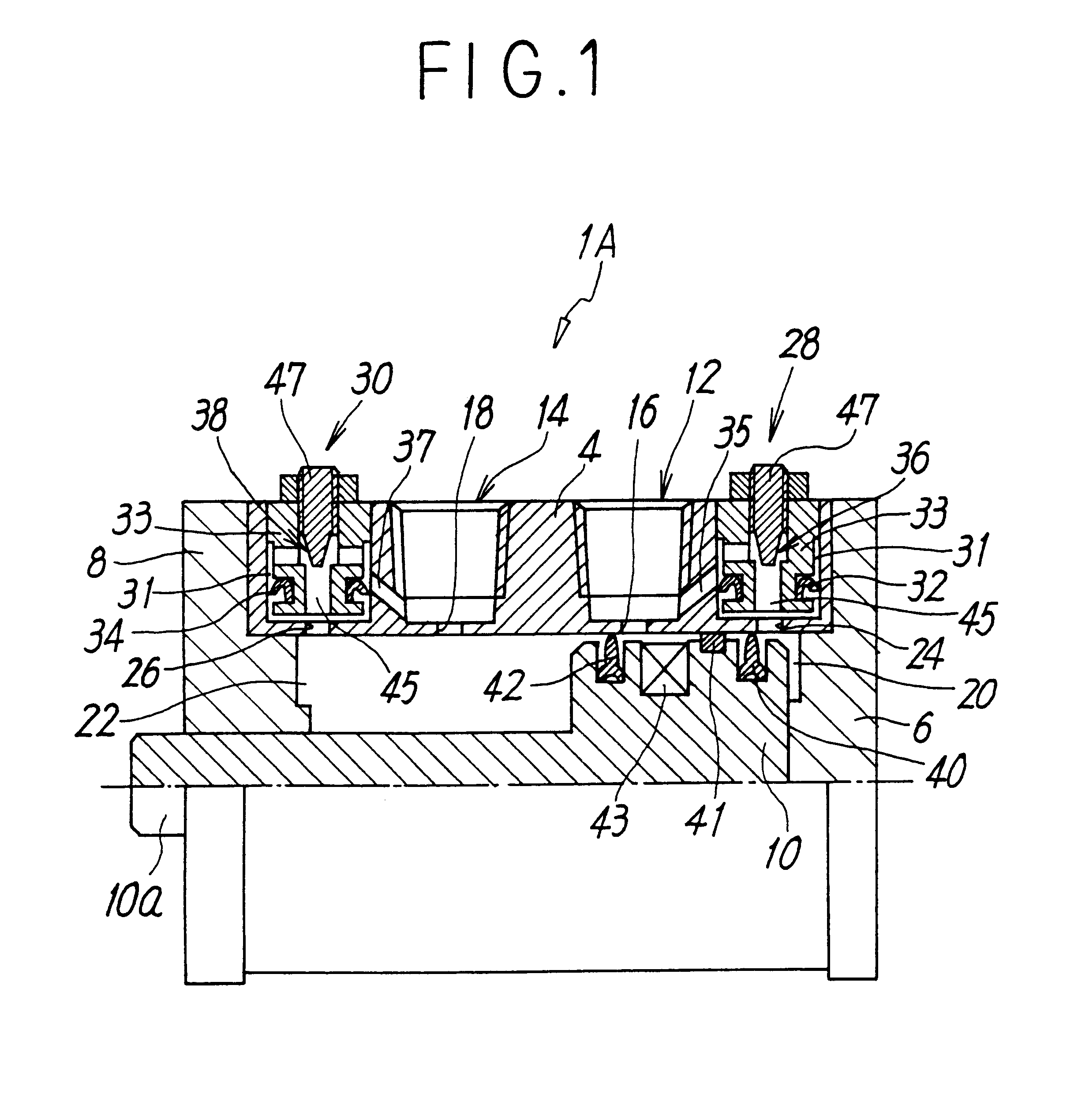
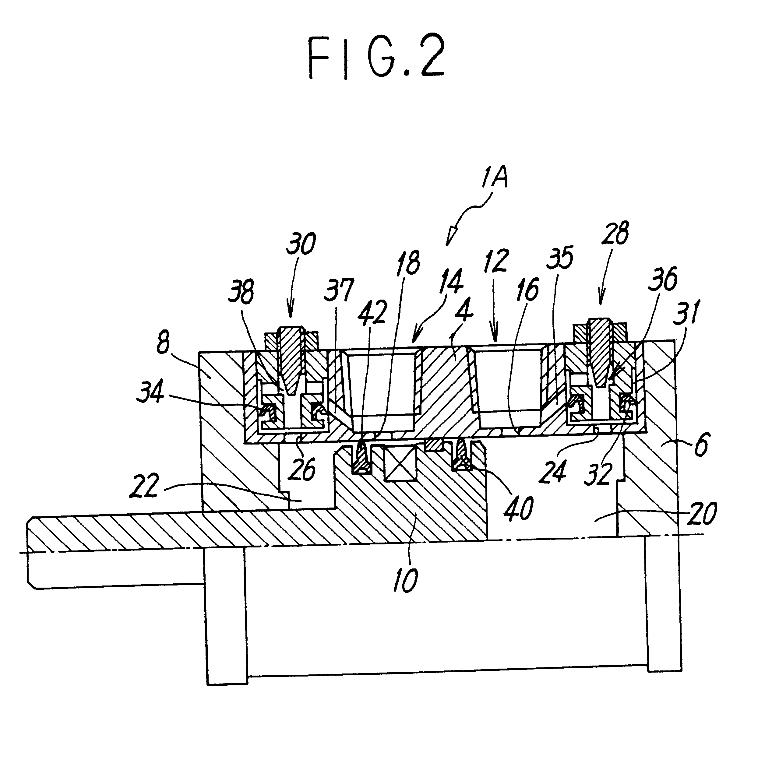
FIGS. 1 and 2 show an air cylinder with a cushion mechanism according to the present invention. The air cylinder 1A includes a cylinder tube 4, both ends thereof being blockaded by a head cover 6 and a rod cover 8, respectively, a piston 10 which reciprocates within the cylinder tube 4 sliding air-tightly, and a piston rod 10a connected to the piston 10.

In the vicinities of ends in the head and rod sides of the cylinder tube 4, two ports 12 and 14 for supplying and discharging compressed air are disposed, respectively. These ports 12 and 14 communicate with a pair of pressure chambers 20 and 22 defined in the both sides of the piston 10, via openings 16 and 18, respectively. The piston 10 is driven to be reciprocated in the cylinder tube 4 by supplying and discharging compressed air to / from the pressure chambers 20 and 22 from / to the ports 12 and 14 via the openings 16 and 18, respectively. In the substantial end portions of the cylinder tube 4 closer to the terminal ends of the str...

fourth embodiment

In the fourth embodiment, in the state shown in FIG. 5, when compressed air is supplied to the port 12, the compressed air mainly flows in the clearance of the outer surface of the piston 10 from the opening 16 so as to enter the pressure chamber 20 by extending the packing ring 50 by force, although it also flows in the pressure chamber 20 from the throttling mechanism 36 adding gradually, so that the piston 10 can start at the expected speed.

After the above-mentioned packing ring 50 passed through the opening 16 of the port 12 by the some movement of the piston 10, the compressed air from the port 12 directly flows in the pressure chamber 20 through the opening 16 and afterward the packing ring 50 functions as piston packing maintaining air-tightness of the pressure chamber 20.

When the piston 10 approaches the stroke end, the packing ring 54 in the front side of the moving direction functions as cushioning packing, that is, just like in the first embodiment, the discharging path i...

fifth embodiment

In the fifth embodiment, the packing ring 40 in the two packing rings 40 and 42 attached in the piston 10 is disposed in the side in which speed-regulating means 28 is arranged so as to serve the function as piston packing and cushion packing in common while the packing ring 42 in the opposite side functions only as piston packing.

In addition, FIG. 6 shows speed-regulating means 28 as a configuration corresponding to the first embodiment; it may be formed to correspond to any of the second to fourth embodiments. However, when speed-regulating means 28 is formed to correspond to the fourth embodiment, among three packing rings 50, 52, and 54 shown in FIG. 5, the packing ring 54 disposed in the end side in which speed-regulating means is not arranged is omitted.

The air cylinder with a cushion mechanism according to the present invention is not needed to form a long cushion ring in the piston and a long empty room for inserting the cushion ring, so that the longitudinal length of the c...


PUM


Abstract

A small-sized and inexpensive air cylinder with a cushion mechanism having a simple structure is provided. Therefore, discharge outlets for discharging cushioning air are disposed in positions closer to ends of the stroke than the openings of the ports in the cylinder tube, respectively, and check valves and throttling mechanisms are arranged in parallel between discharge outlets and ports, respectively. On the outer peripheral surface of the piston, one of the piston packing rings is disposed in one position which does not pass through the opening of the port while another of the piston packing rings is disposed in another position which passes through the opening but does not pass through discharge outlet, when the piston reaches the terminal ends of the stroke.

Description

The present invention relates to an air cylinder having a cushion mechanism for absorbing a shock due to the energy of inertia when a piston of the cylinder stops at the stroke terminal end thereof.DESCRIPTION OF THE RELATED ARTIn an air cylinder having a cylinder tube and a piston sliding within the cylinder tube, a cushion mechanism has been well known in which cushioning air is temporarily encupsulated in an air chamber in the exhaust side to be pressurized during the piston operation to thereby decelerate the piston using the exhaust-air pressure, resulting in stopping it in a cushioning manner at the stroke end. In this conventional air cylinder, an air discharge path is blocked by inserting a cushion ring disposed in the piston side into cushion packing within the piston tube before the stroke end so as to lead the discharging air to a throttle valve. Thereby, the back pressure of the piston converts the kinetic energy of the piston to the air compressing energy in accordance ...

Claims


Application Information

Patent Timeline
Patent Type & Authority Patents(United States)
IPC IPC(8): F15B15/22F15B15/00F16K15/14
CPCF16K15/142F15B15/224F15B15/22
Inventor HIRANO, AKIHIRONISHIMATA, KENICHI
Owner SMC CORP
Why Eureka
Try Eureka