
Anti-theft door monitoring device

A technology for monitoring devices and anti-theft doors, which is applied to windows/doors, special equipment for doors/windows, and televisions. It can solve problems such as large storage disk usage, incomplete camera images, and the impact of police cracking cases. It achieves high practicability, Make up for the effect of limited camera range and simple and reasonable design

Active Publication Date: 2018-09-18
浙江神将门业有限公司
View PDF6 Cites 5 Cited by
  • Summary
  • Abstract
  • Description
  • Claims
  • Application Information

AI Technical Summary

Problems solved by technology

[0003] The common anti-theft door monitoring device is installed on the door frame by screws for anti-theft shooting. However, this type of anti-theft monitoring device needs to keep working after installation, which seriously affects its working life, and has a large power consumption and storage disk Due to defects such as large occupancy, when thieves knock on the door and steal, they often bow their heads to avoid the monitoring device or cover their faces, resulting in incomplete images captured by the camera and affecting the police to solve the case

Method used


Image

  • Anti-theft door monitoring device
  • Anti-theft door monitoring device
  • Anti-theft door monitoring device

Examples


Embodiment Construction

[0022] The following will clearly and completely describe the technical solutions in the embodiments of the present invention with reference to the accompanying drawings in the embodiments of the present invention. Obviously, the described embodiments are only some, not all, embodiments of the present invention. Based on the embodiments of the present invention, all other embodiments obtained by persons of ordinary skill in the art without making creative efforts belong to the protection scope of the present invention.

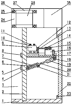
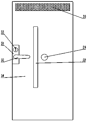
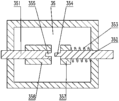
[0023] see Figure 1~3 , in an embodiment of the present invention, an anti-theft door monitoring device includes a transmission chamber 3, an upper slider 8, a camera 16, a motor base 24 and a power switch 35, the motor base 24 is arranged on the top of the transmission chamber 3, and the motor base 24 The first motor 28 is arranged inside, the upper and lower ends of the first motor 28 are provided with first motor fixing sleeves 27, the first screw rod 2 is...


PUM


Abstract

The invention discloses an anti-theft door monitoring device. The anti-theft door monitoring device comprises a transmission chamber, an upper sliding block, a camera, a motor base and a power supplyswitch; the motor base is arranged at the top of the transmission chamber, a first motor is arranged in the motor base, a first lead screw is arranged on the lower portion of the first motor, and theupper sliding block and a lower sliding block are arranged on the first lead screw in a sleeving mode; a sliding rail is arranged on the right side of the upper sliding block, the camera is arranged on the upper portion of the sliding rail, fixing blocks are arranged at the upper end and the lower end of the right side of the transmission chamber correspondingly, and protective glass is arranged on the right sides of the fixing blocks and fixedly connected with the right sides of the fixing blocks; and the power supply switch is arranged on the upper right portion of the transmission chamber,the transmission chamber is arranged in an anti-theft door, and the protective glass is arranged in the front side wall of the anti-theft door. The anti-theft door monitoring device is simple and reasonable in structural design, operation is convenient and fast during using, and practicability is quite high; and according to the anti-theft door monitoring device, the camera can be driven by the motor to conduct scan and shoot, thus the whole body of a thief is shot, the defect that the shooting range of the camera is not wide can be made up, and the situation that judgment is influenced due toincomplete shooting pictures is prevented.

Description

technical field [0001] The invention relates to a monitoring device, in particular to a monitoring device for an anti-theft door. Background technique [0002] Common anti-theft doors are equipped with anti-theft locks, which can resist abnormal opening under certain conditions within a certain period of time, have certain safety protection performance and meet the corresponding anti-theft safety level. When users use anti-theft doors, they often install monitoring devices on the top of the anti-theft doors to further protect the safety of property in the house. The monitoring devices can capture the appearance of the thief before he enters the door, so as to facilitate the police to solve the case. [0003] The common anti-theft door monitoring device is installed on the door frame by screws for anti-theft shooting. However, this type of anti-theft monitoring device needs to keep working after installation, which seriously affects its working life, and has a large power con...

Claims


Application Information

Patent Timeline
IPC IPC(8): E06B7/28H04N7/18
CPCE06B7/28H04N7/186
Inventor 徐少坤
Owner 浙江神将门业有限公司
Learn More