Vibrating gyroscope

a gyroscope and vibration circuit technology, applied in the direction of generator/motor, turn-sensitive devices, instruments, etc., can solve the problems of increasing the cost of vibration circuit and the inability to detect angular velocity in multiple directions, and achieve the effect of improving the detection accuracy and accuracy

Inactive Publication Date: 2001-08-28
MURATA MFG CO LTD
View PDF7 Cites 37 Cited by
  • Summary
  • Abstract
  • Description
  • Claims
  • Application Information

AI Technical Summary

Problems solved by technology

The vibration circuit is expensive, thereby increasing costs to detect angular velocities in multiple directions.

Method used


Image

  • Vibrating gyroscope
  • Vibrating gyroscope
  • Vibrating gyroscope

Examples


Embodiment Construction

Hereinafter, the preferred embodiments of the present invention are explained in detail with reference to the drawings.

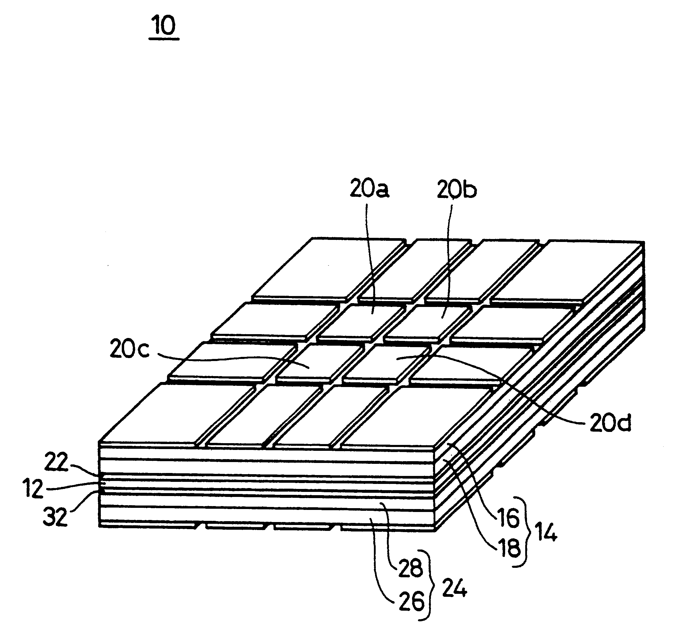
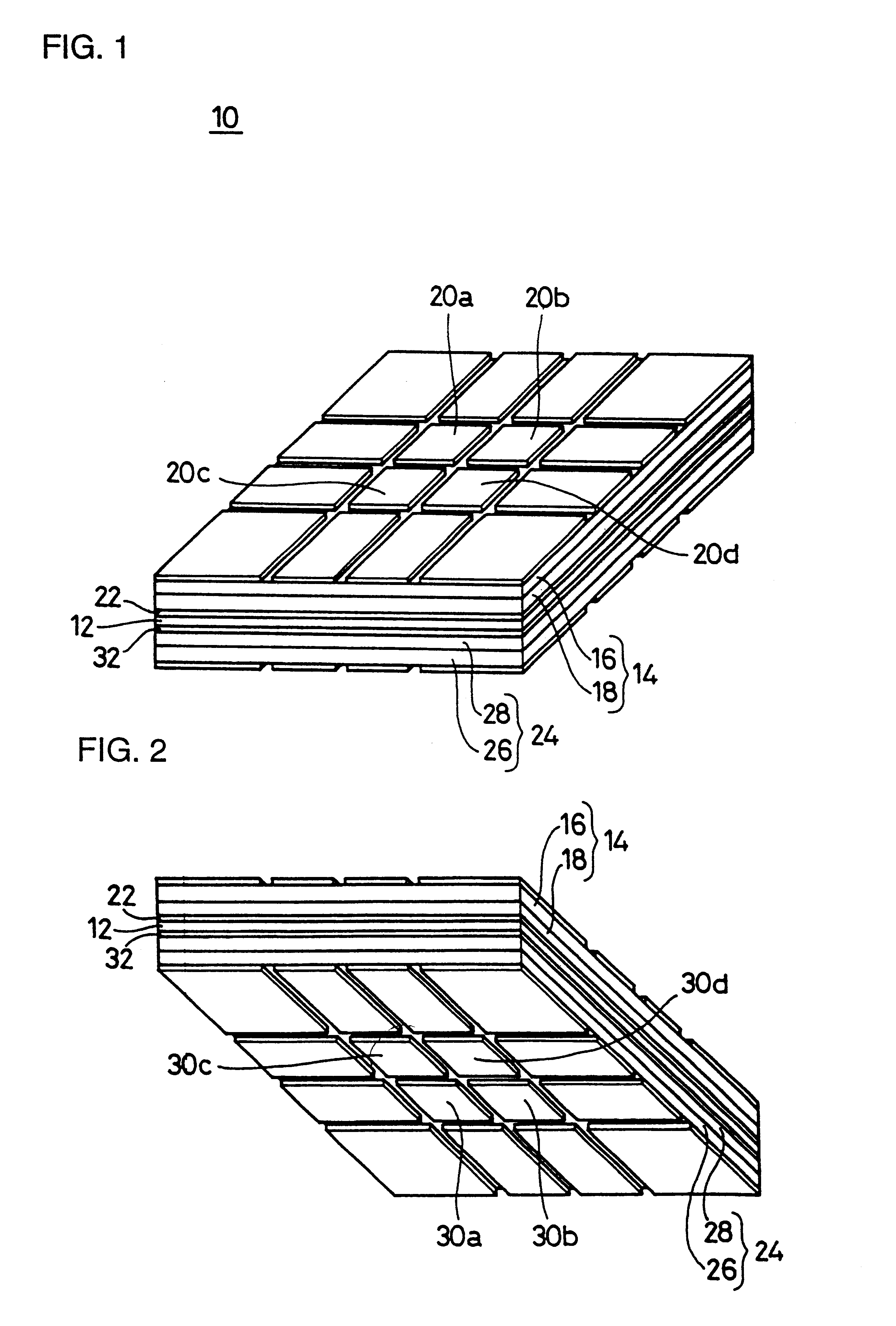
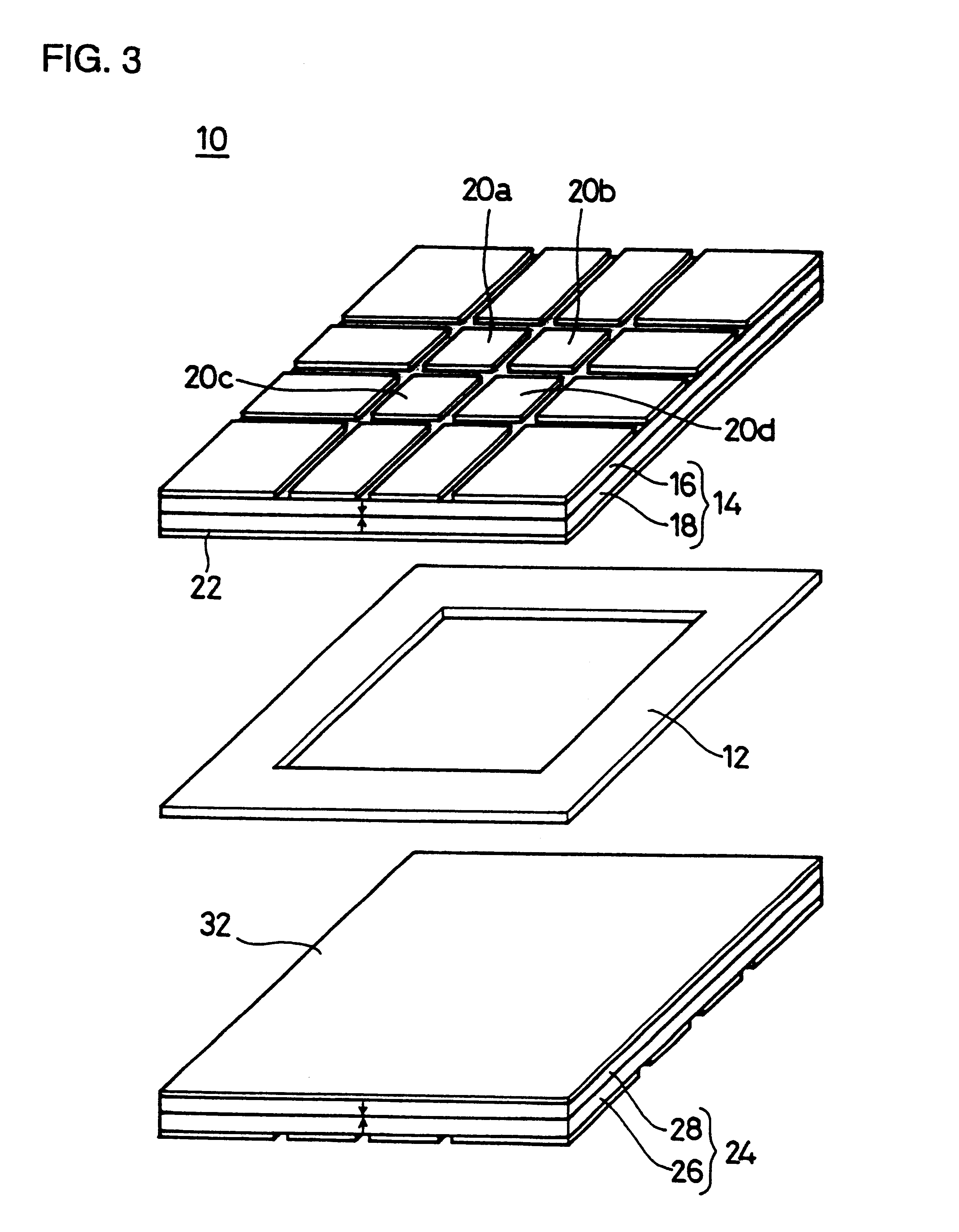
FIG. 1 is a perspective view showing an example of a vibrating gyroscope of the present invention. FIG. 2 is a perspective view taken at a different angle of the vibrating gyroscope shown in FIG. 1; and FIG. 3 is an exploded perspective view thereof. A vibrating gyroscope 10 includes an intermediate member 12. As shown in FIG. 3, the intermediate member 12 is formed in a frame shape having a through opening in its central portion. A vibrating plate 14 is formed on one of the opposing sides of the intermediate member 12. The vibrating plate 14 is formed, for example, by coupling piezoelectric substrates 16 and 18. As indicated by arrows in FIG. 3, the piezoelectric substrates 16 and 18 are polarized so as to oppose each other in the thickness direction.

On the piezoelectric substrate 16, there are formed 16 sectional electrodes, of which four electrodes 20a, 20b, 20c,...


PUM


Abstract

A vibrating gyroscope includes two planar vibrating plates arranged to oppose each other. The two vibrating plates vibrate under buckling vibration mode and a second-order bending vibration mode which is degenerated with or close to the buckling vibration mode. The vibrating gyroscope detects Coriolis force by detecting displacements in amplitude balance of the second-order bending vibration modes generated when an angular rotation velocity around an axis parallel to surfaces of the vibrating plates is applied.

Description

1. Field of the InventionThe present invention relates to a vibrating gyroscope, and more particularly to a vibrating gyroscope used, for example, to detect angular velocities for prevention of camera shake.2. Description of the Related ArtFIG. 11 is a perspective view of an example of a conventional vibrating gyroscope. A vibrating gyroscope 1 includes a vibrating body 2 in, for example, the shape of a regular triangle. As seen in FIGS. 11 and 12, three peripheral surfaces of the vibrating body 2 have piezoelectric elements 3a, 3b, and 3c, respectively. To use the vibrating gyroscope 1, as shown in FIG. 12, for example, a vibration circuit 4 is connected between the piezoelectric elements 3a and 3b and the piezoelectric element 3c. Also, the piezoelectric elements 3a and 3b are connected to a detection circuit 5. The detection circuit 5 includes, for example, a differential circuit, a synchronous detection circuit, a smoothing circuit, and a DC amplifying circuit.In the vibrating g...

Claims


Application Information

Patent Timeline
Patent Type & Authority Patents(United States)
IPC IPC(8): G01C19/56G01C19/00G01C19/567G01C19/5719
CPCG01C19/5719G01C19/00
Inventor ISHITOKO, NOBUYUKIFUJIMOTO, KATSUMI
Owner MURATA MFG CO LTD
Why Eureka
Try Eureka