Method and apparatus for on-line monitoring of log sawing

a log and monitoring technology, applied in the field of split detection apparatus, can solve the problems of reducing the value of the log itself, one end of the log is not supported, and the split creation of splits when cu

Inactive Publication Date: 2001-10-02
UNITED STATES OF AMERICA AS REPRESENTED BY THE SEC OF AGRI THE +1
View PDF34 Cites 19 Cited by
  • Summary
  • Abstract
  • Description
  • Claims
  • Application Information

AI Technical Summary

Problems solved by technology

When logs are sawn to size in the field using commercial harvesters, they are often subject to the creation of splits when cut.
This is because one end of the log is unsupported during the cutting operation.
The splits are undesirable, introduce defects in the lumber that is

Method used


Image

  • Method and apparatus for on-line monitoring of log sawing
  • Method and apparatus for on-line monitoring of log sawing
  • Method and apparatus for on-line monitoring of log sawing

Examples


Embodiment Construction

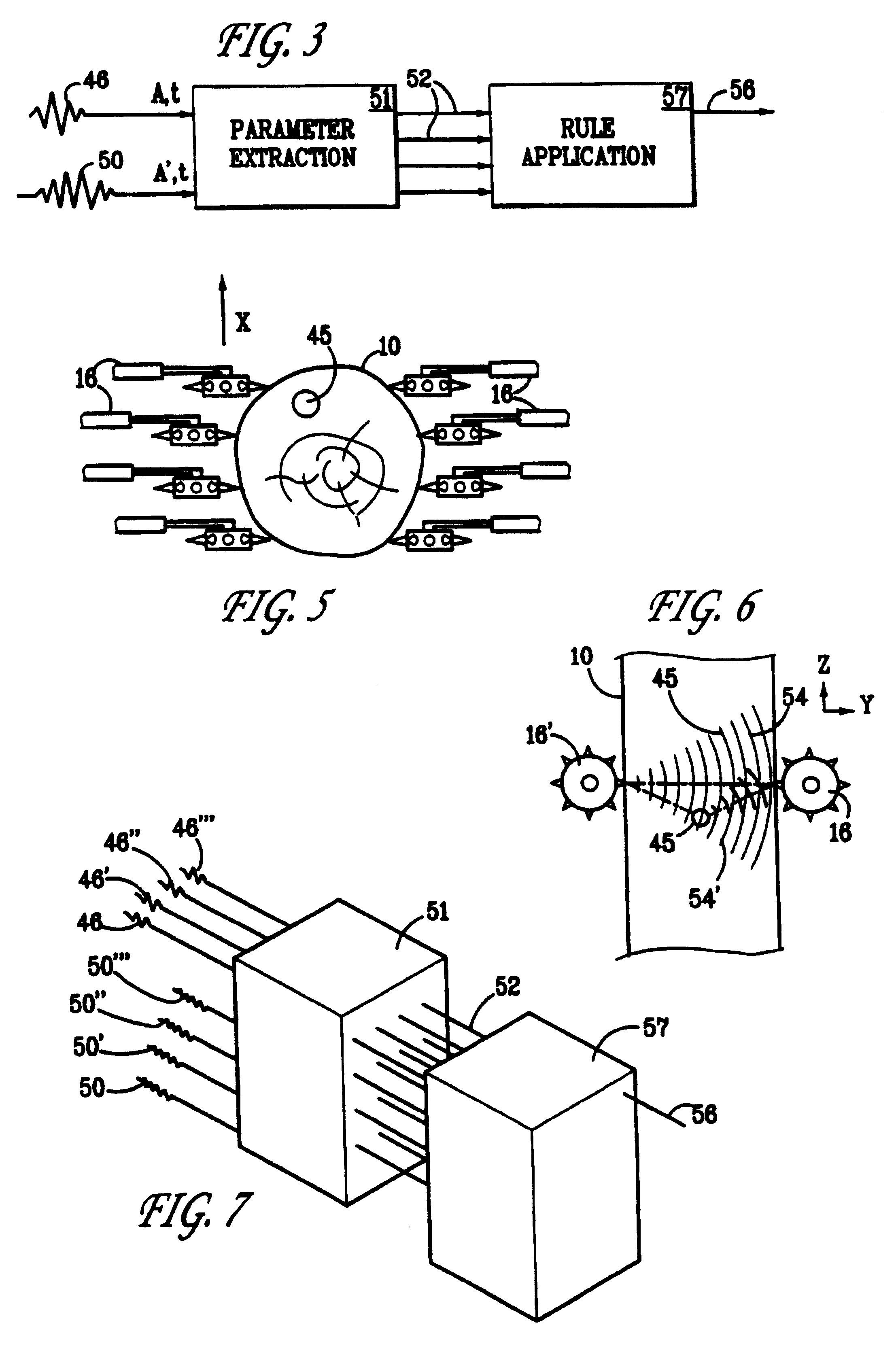
Measurements were made of a log prior to cutting ("undisturbed") and after cutting, at various angles with respect to a split as indicated in the following Table II. The measurements were time of flight (TOF) as detected by an amplitude threshold (TOFa) or an energy threshold (TOFe). Pulse length (PL) using IEC standard 1157 and insertion loss (IL) were also measured.

The zero degree reading corresponds closely to the undisturbed reading however the 45.degree. and 90.degree. readings differ significantly from the baseline readings. The changes in pulse length and times of flight are by factors of 1.5 to 2.5; the insertion loss change is over 20 db, or 100 to 1.

Table III below provides successive readings of the same parameters taken along the log at increasing distances from the cut face.

In this case the three parameters change independently. The times of flight change quickly as a function of distance from the cut face because any sound transmission around the cut will reach the rec...


PUM

PropertyMeasurementUnit
Distanceaaaaaaaaaa
Distanceaaaaaaaaaa
Distanceaaaaaaaaaa

Abstract

Ultrasonic techniques are applied to the measurement of wooden members to detect splitting during sawing operations and thereby allow modification of sawing technique or change in saw cut placement.

Description

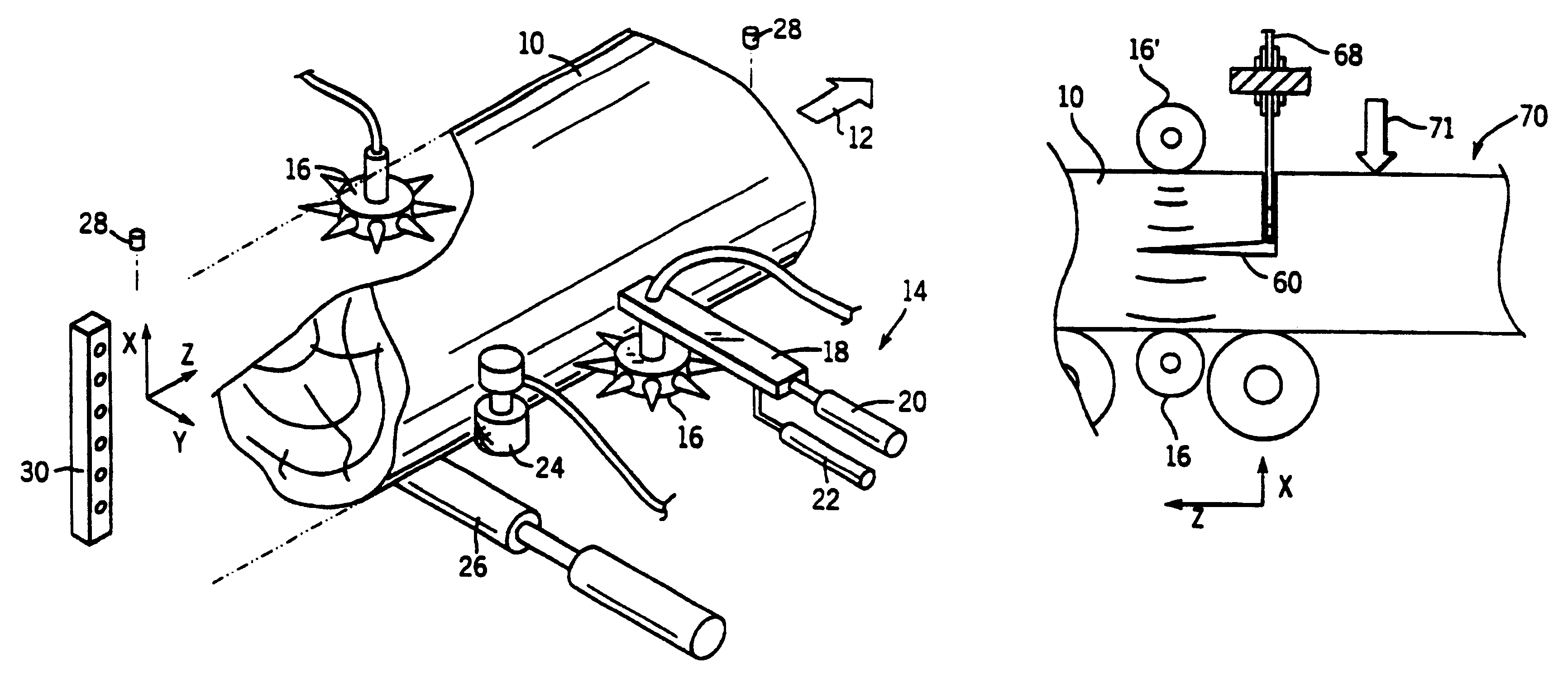
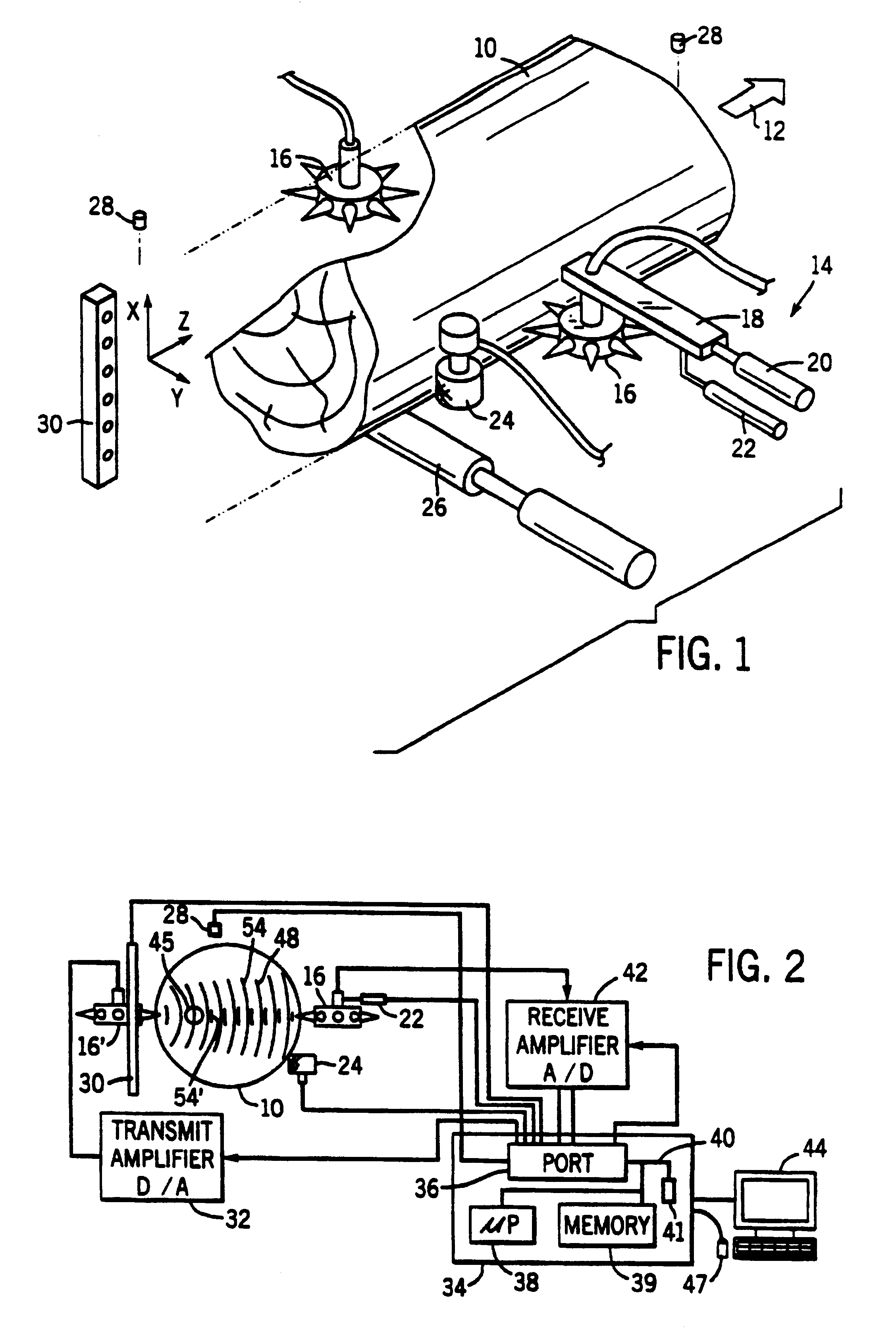
BACKGROUND OF THE INVENTIONThe present invention relates to an apparatus for the detection of splits in logs and other wooden members, and specifically to an apparatus employing ultrasonic energy to detect and characterize such splits. The wooden members may be trees, logs, beams, planks, lumber, boards or wood composites and the like.When logs are sawn to size in the field using commercial harvesters, they are often subject to the creation of splits when cut. This is because one end of the log is unsupported during the cutting operation. Splits also occur when the tree is initially felled. The splits are undesirable, introduce defects in the lumber that is sawn from the logs, and thereby reduce the value of the log itself. A recent examination of the problem indicates that up to 70% of logs harvested in this manner contain splits. If the problem is detected in the field at the time of sawing, then either the operator can modify his / her practice to reduce this incidence, or the logs...

Claims


Application Information

Patent Timeline
IPC IPC(8): G01N29/24B23D59/00B26D5/00B27B1/00B27B31/06
CPCB23D59/001B27B1/007G01N2291/0238G01N2291/0421G01N2291/0422Y10T83/155Y10T83/178
Inventor SCHAFER, MARK E.ROSS, ROBERT J.
Owner UNITED STATES OF AMERICA AS REPRESENTED BY THE SEC OF AGRI THE
Why Eureka
Try Eureka