Valve controlled dispensing closure

Inactive Publication Date: 2001-10-09
BERRY PLASTICS CORP
View PDF17 Cites 83 Cited by
  • Summary
  • Abstract
  • Description
  • Claims
  • Application Information

AI Technical Summary

Problems solved by technology

The push body valve closures of the prior art generally include relatively complex and involved structure which is difficult to

Method used


Image

  • Valve controlled dispensing closure
  • Valve controlled dispensing closure
  • Valve controlled dispensing closure

Examples


Embodiment Construction

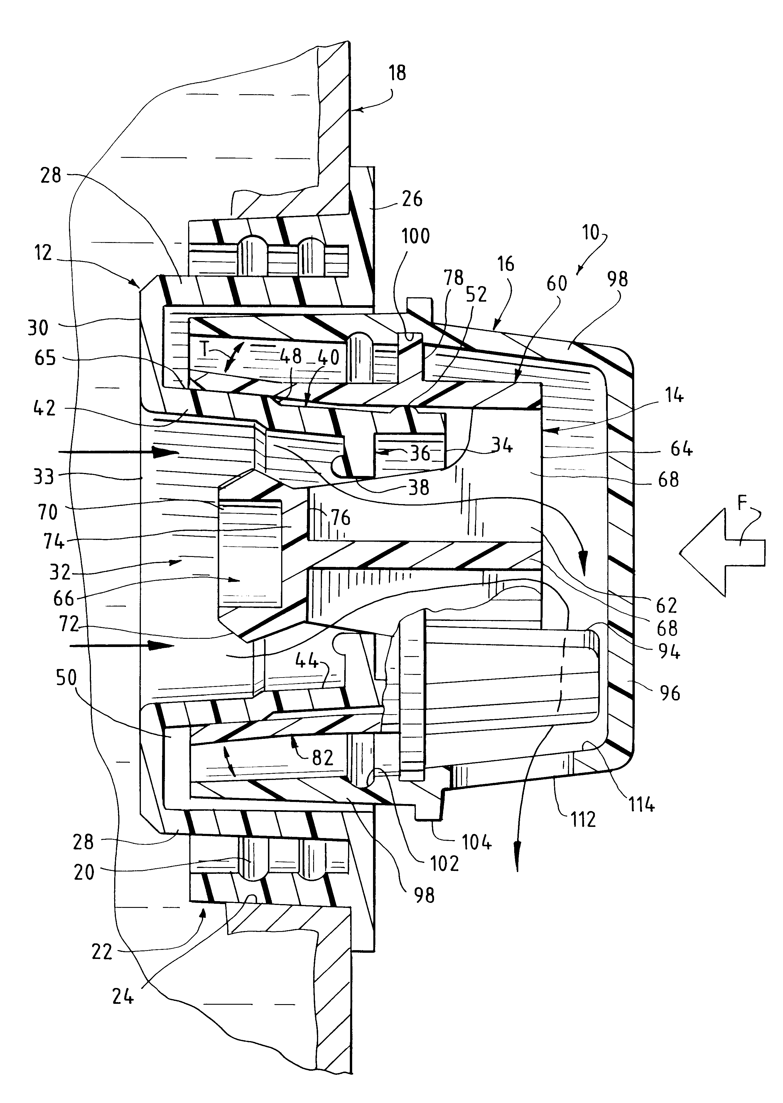
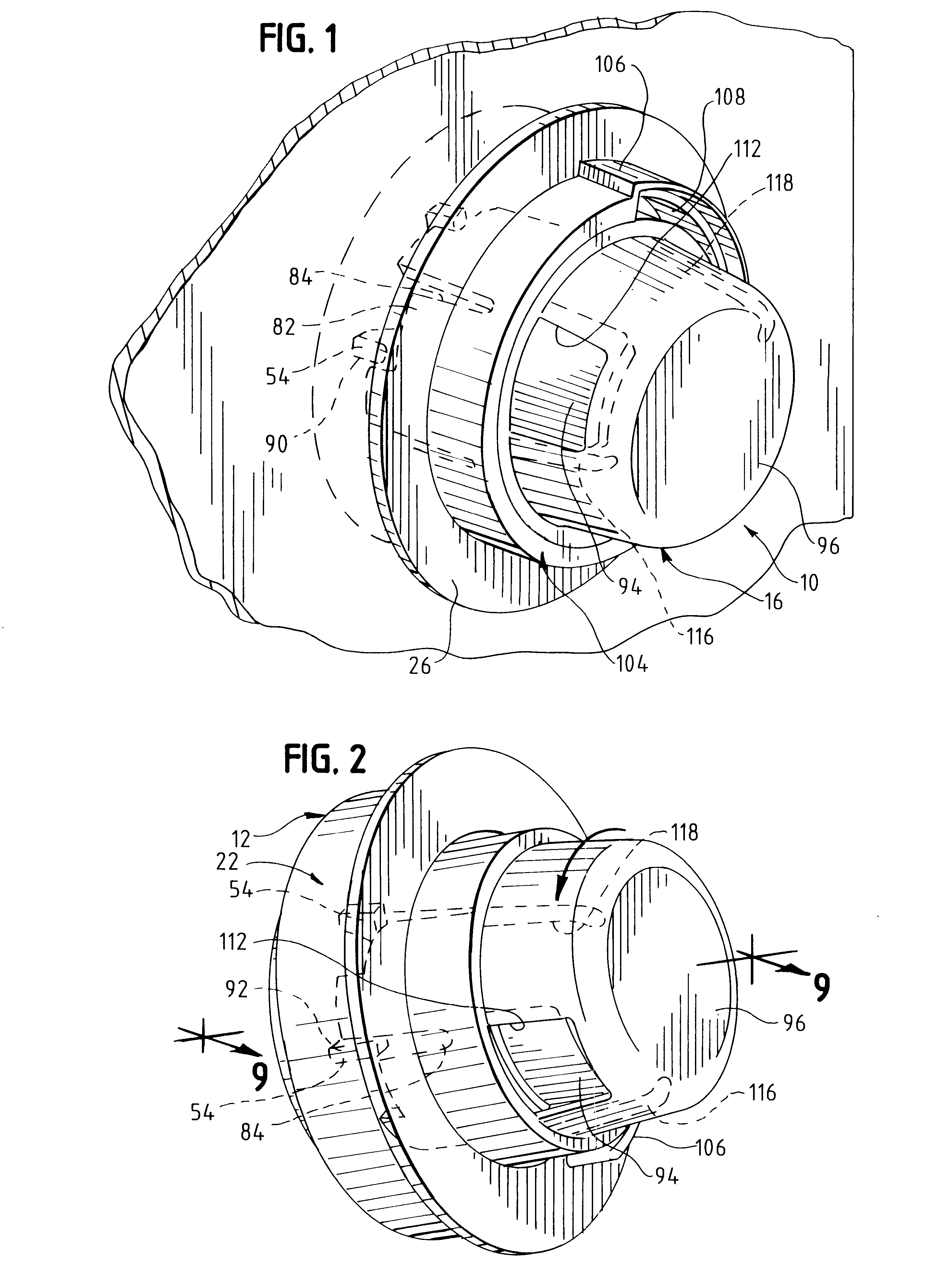
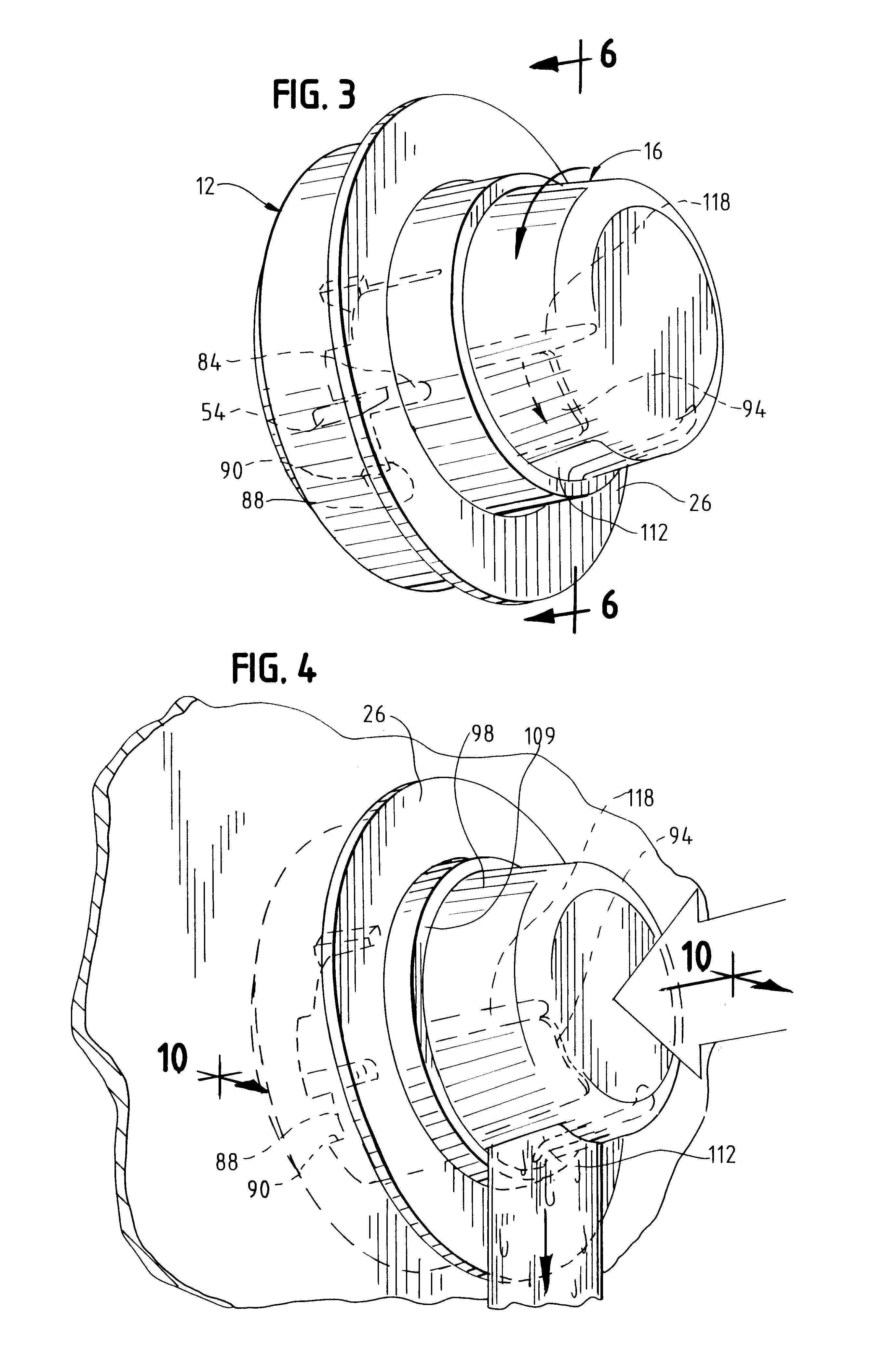
Referring to the drawings, the dispensing closure 10 of the invention, preferably formed of molded plastic material, includes three cooperating components, base 12, valve 14 engaged upon the base 12, and cap 16 overlying valve 14 for manipulation of valve 14 relative to base 12. The base 12 is adapted for attachment to the mouth of a container 18 in a known manner, such as by screw threads 20 formed on the inner surface of a depending outer skirt 22 of base 12 which mate with like threads on the mouth of the container. Alternatively, and as illustrated in FIGS. 9 and 10, the base skirt 22 can be pressure-fit within a smooth-bore container opening 24.

Base 12 includes an annular flange 26 overlying and extending radially beyond the base skirt 22 for, as may be required, engagement with the body of the container about the opening therein. This flange 26 also projects radially inward of the skirt 22 and terminates at an integral depending inner skirt 28 generally parallel to and inwardl...


PUM


Abstract

A push valve dispensing closure including a base mountable to the mouth of a container, a valve mounted within the base and a cap cooperatively engaged upon the base for rotational movement of the valve relative to the base between locked and unlocked positions, and, in the unlocked position, between a first closed position and a second open position with respect to the base. The base is formed with a product dispensing channel having a wall with a generally conical-shaped cross-sectional configuration and the valve has depending spring-action circumferential flange segments formed thereon for cooperative engagement with the conical-shaped wall. The cap includes a discharge orifice closed by a panel on the valve with rotation of the cap relative to the valve, after movement of the valve to the unlocked position, opening the orifice.

Description

1. Field of the InventionThis invention relates generally to dispensing closures for containers, and more particularly, to such closures which, after being opened, automatically return to their closed position to prevent unintentional dispensing of product from such containers.2. Description of the Prior ArtPush body closures are known in which a cap or spout having a dispensing aperture is positioned upon a base with cooperative elements therebetween to permit the closure to be opened or closed by disengagement or engagement of the cooperative elements. The base is affixed to the mouth of a product container, such as a water bottle. When a force is applied to the cap to move the cap with respect to the base, such as by pushing on the cap with the lips of a user, the cooperative elements between the cap and base are caused to disengage and thereby open the closure and permit the product, such as water, in the container to pass through a dispensing aperture in the cap and be dispense...

Claims


Application Information

Patent Timeline
IPC IPC(8): B65D47/04B65D47/24B65D50/06B65D50/00
CPCB65D47/248B65D50/061
Inventor BERGE, GARYSTONEBERG, THOMAS C.
Owner BERRY PLASTICS CORP
Why Eureka
Try Eureka