
Matched-lag filter for detection and communication

a technology of matched lag and detection and communication, applied in the direction of direction finders using radio waves, transmission monitoring, instruments, etc., can solve the problems of enhancing the probability of detection and the inability to detect as large as desired, and achieves enhanced detection probability, reliable modeling, and high detection probability

Inactive Publication Date: 2001-10-16
SPIESBERGER JOHN LOUIS
View PDF2 Cites 28 Cited by
  • Summary
  • Abstract
  • Description
  • Claims
  • Application Information

AI Technical Summary

Problems solved by technology

If the energy changes by more than noise alone would likely allow, one decides that one or more signals are present, with some accompanying probability of error.
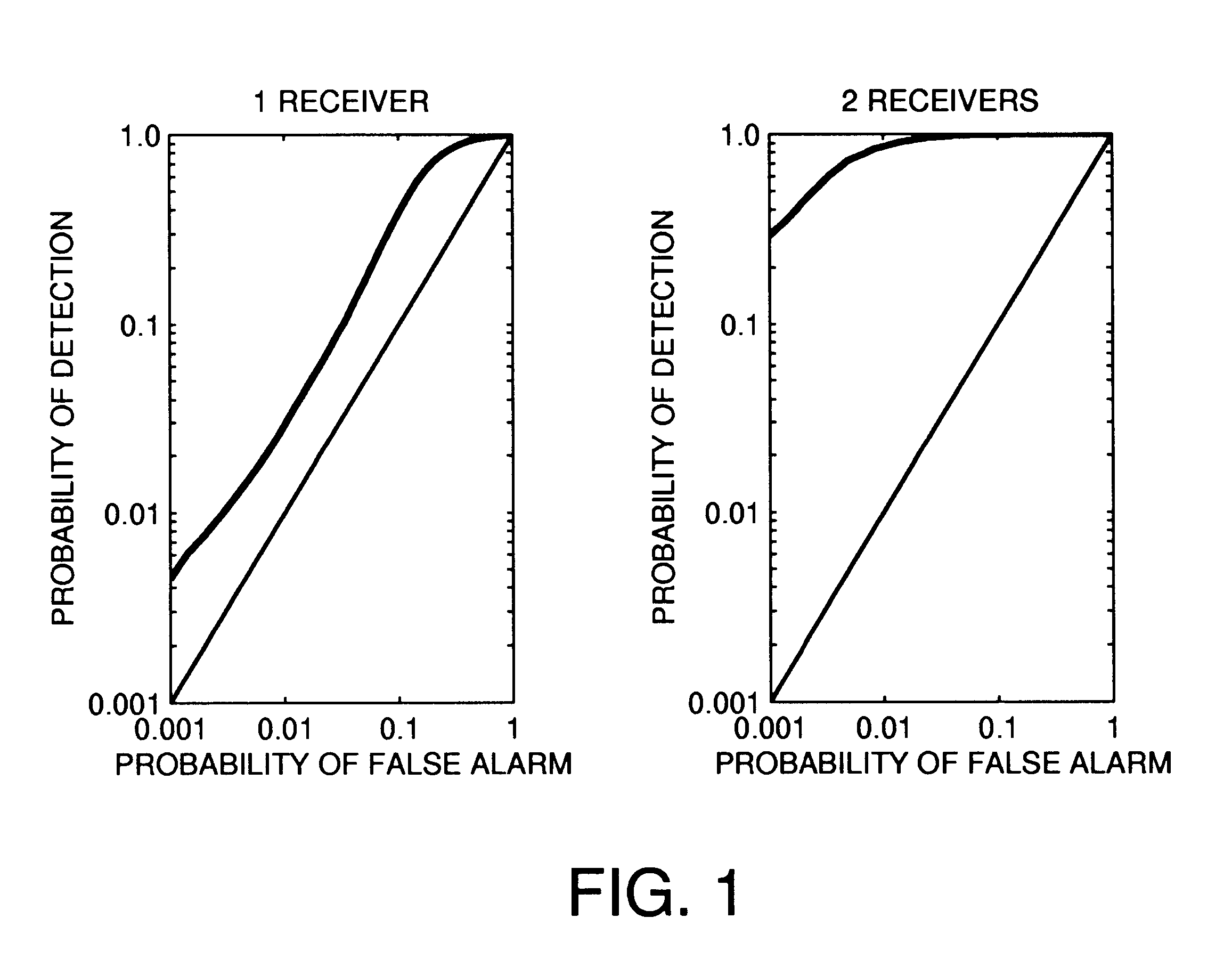
The main deficiency of the energy detector is that is probabilities of detection may not be as large as desired.

Method used


Image

  • Matched-lag filter for detection and communication
  • Matched-lag filter for detection and communication
  • Matched-lag filter for detection and communication

Examples


case 1

In case 1, .tau. and N are even. There cannot be a signal at bin .tau. / 2 otherwise N would have to be odd. Work with bins .tau. / 2+1 through .tau.-1, which are referred to as the upper half. Half of the remaining N-2 remaining signals must go in the upper half with the remaining going in the lower half to maintain symmetry according to Eq. (B1). The upper half contains ##EQU69##

bins, and there are, ##EQU70##

ways of arranging the ##EQU71##

samples among them. In case 2, .tau. is even and N is odd. There must be a signal in bin .tau. / 2. The are ##EQU72##

upper half bins, ##EQU73##

through .tau.-1. They are filled with ##EQU74##

signals which can be done in, ##EQU75##

ways to make a symmetrical set. In case 3, .tau. is odd and N is even. There cannot be a signal in bin .tau. / 2. There are ##EQU76##

upper half bins, ##EQU77##

through .tau.-1. These are filled with ##EQU78##

signals which can be done in, ##EQU79##

ways to make a symmetrical set. In case 4, .tau. and N are odd. It is impossible to c...


PUM


Abstract

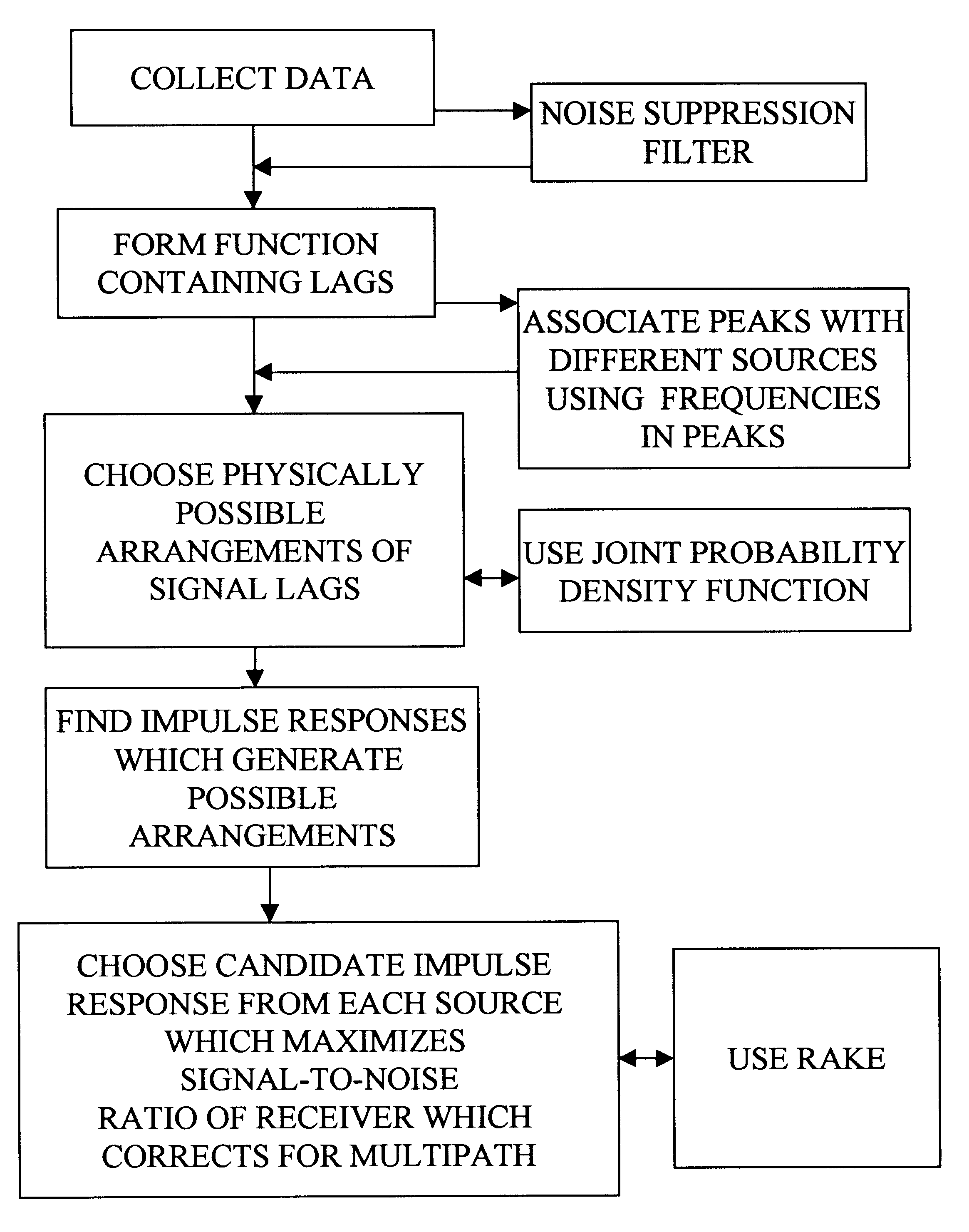
A detection problem is introduced for a source of some bandwidth and unknown waveform and emission time in the presence of noise of uncertain variance. The signal travels to the receivers along paths whose delays may be unknown. Using a new receiver called a "matched-lag filter," the presence or absence of the signal is estimated from the auto- and cross-correlation functions of the received signals. The use of correlation functions provides the first stage of gain in signal-to-noise ratio, like a matched filter, because the paths are assumed to be partially coherent with one another. The second stage achieves additional gain by searching only over the physically possible arrangements of signals in the auto- and cross-correlation functions. These stages enable the matched-lag filter to behave like a matched filter within a matched filter. In a simple case, simulations of the matched-lag filter yield probabilities of detection that are, with one and two receivers, 4.5 to 290 times respectively that obtained from the alternative energy detector at a false-alarm probability of 0.001. The matched-lag filter has applications to communications and the detection of broadband signals such as from animals, vehicles, ships, nuclear blasts, and seismic events, and blind estimation of the impulse response of a multipath channel.

Description

BACKGROUND-FIELD OF THE INVENTIONIn general, the present invention relates to the utilization of auto-correlation and cross-correlation functions in methods for detecting and communicating data from one or more sources of a primary signal when the primary signal has a waveform that is not known at one or more receivers at the outset.BACKGROUND-DESCRIPTION OF PRIOR ARTThe energy detector is the traditional method for detecting signals of uncertain emitted waveform (Whalen, Detection of signals in noise, Academic Press, New York, pp. 411, 1971). If the waveform was known, one could use the matched filter to enhance the detection of the signal (North, RCA Laboratory Report PTR-6C; (reprinted in Proc. I.E.E.E. 51, 1016-1027, 1963), 1943). However without knowledge of the waveform, the energy detector is the only prior alternative. The energy is the sum of the squares of samples from the received signal. If the energy changes by more than noise alone would likely allow, one decides that ...

Claims


Application Information

Patent Timeline
Patent Type & Authority Patents(United States)
IPC IPC(8): G01S3/80G01S3/00
CPCG01S3/8006
Inventor SPIESBERGER, JOHN LOUIS
Owner SPIESBERGER JOHN LOUIS
Learn More