Crosscutter for web materials

a crosscutter and web material technology, applied in the field of web material crosscutter, can solve the problems of not being able to apply acceleration and deceleration, not being able to achieve the effect of large-area transfer

Inactive Publication Date: 2001-10-30
BIELOMATIK LEUZE GMBH & CO
View PDF34 Cites 3 Cited by
  • Summary
  • Abstract
  • Description
  • Claims
  • Application Information

AI Technical Summary

Benefits of technology

The construction of the shaft ends with shaped-on flange consequently permits a very large-area transfer of the forces. Very high contact pressures must act with a nonpositive transfer. They can be applied to a very large surface area, so that despite the high screw forces there is no need to fear overstressing of the light metal material. These frictional forces act due to the fact that substantially the entire circumference (except for the cutter beam recesses) is available for frictional force transfer, whereas the end face portions made from another material, such as the area of the bushes, are set back with respect to the aluminium end face and cannot disturb the frictional force transfer.
Particularly as a result of the combination of the frictional grip and reamed bolts, i.e. through a simultaneous positive and nonpositive connection, an operationally reliable force transfer is possible in this particularly critical case of a connection between two parts of a cutter shaft. The nonpositive transfer ensures that it is completely backlash-free, because it could otherwise work loose. The self-closure by the reamed bolts ensures security on releasing the frictional grip and simultaneously relieves the latter without impairing it.

Problems solved by technology

Compared with a lightweight construction using composite carbon fibre materials (CFKs), it simultaneously permits a direct fitting of the cutter to the cutter block, which would not be possible with CFKs.
In the case of a conventional steel cutter shaft construction, due to the high mass moment of inertia it is not possible to apply the accelerations and decelerations occurring due to the required divergences from the synchronous cut length.
With the conventionally required web widths of approximately 2,000 mm, a cutter shaft with a single cutter on the circumference would only have a travel circle diameter of approximately 160 mm, which would not be possible in the earlier arrangements and materials due to the necessary flexural rigidity.
Thus, in the case of the cutter shaft according to the invention it is possible to choose a form with two cutters on the circumference, which bring the cutter shaft to twice the diameter, which does not permit adequate acceleration values in conventional steel cutter shafts due to the then high mass moment of inertia.
In the case of CFK cutter shafts, which would intrinsically appear suitable for such extreme conditions, for stability reasons steel cutter beds would be required and which as a result of the large cutter travel circle give rise to an excessive mass moment of inertia and whose fixing to the cutter block is problematical and weakens the latter.

Method used


Image

  • Crosscutter for web materials
  • Crosscutter for web materials
  • Crosscutter for web materials

Examples


Embodiment Construction

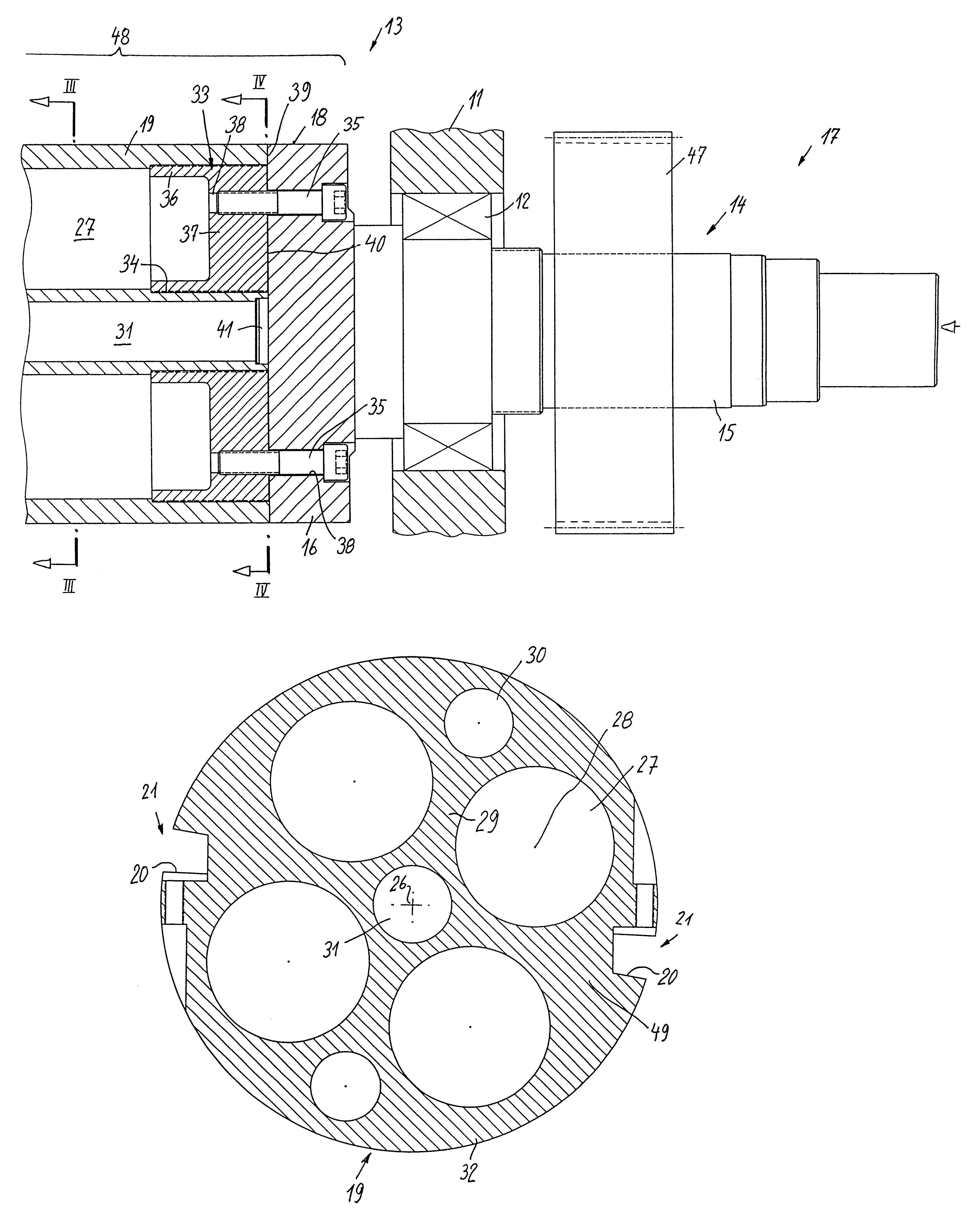
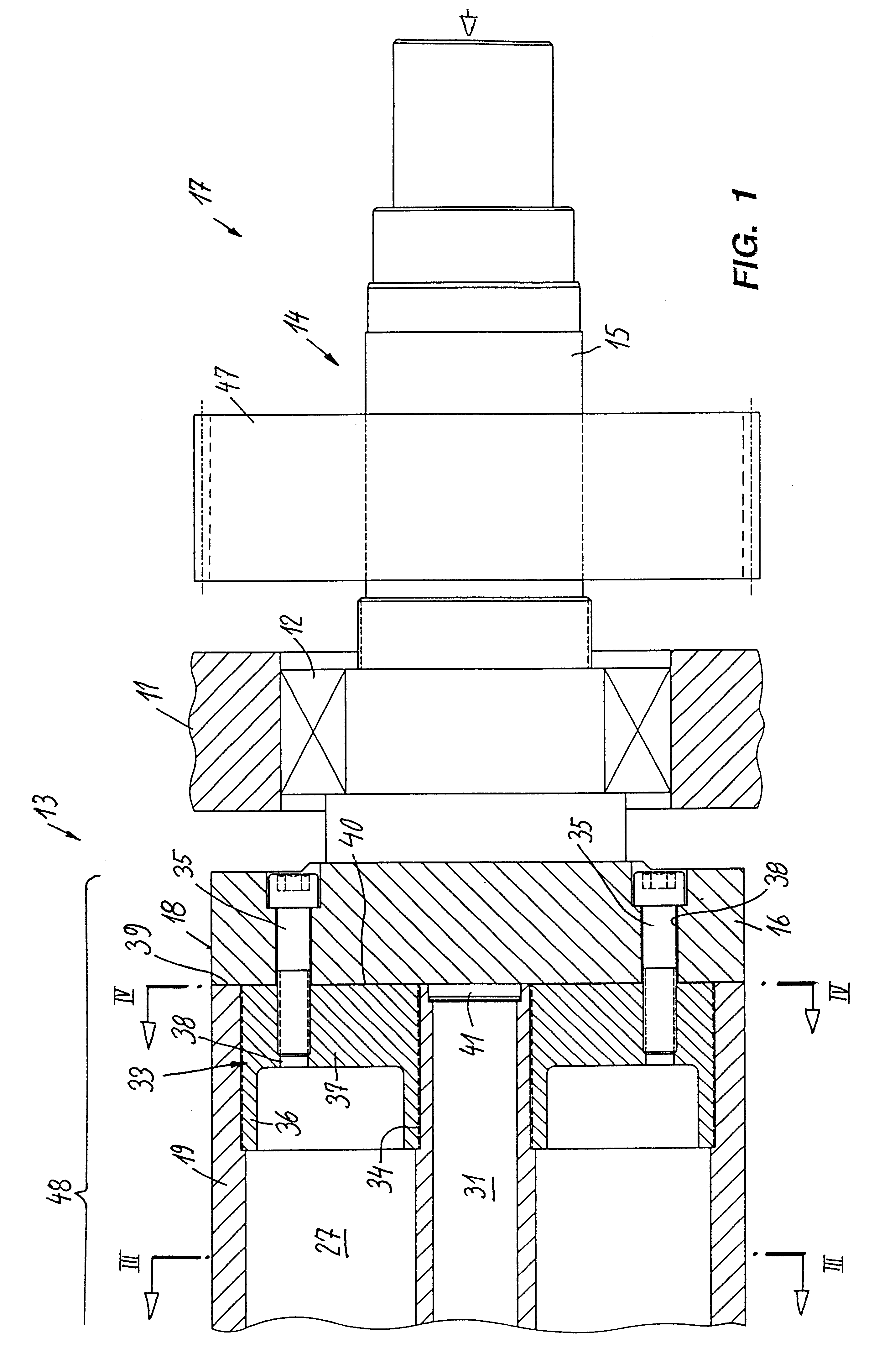
A cutter shaft 13 is mounted in bearings 12 in a crosscutter 11, whereof only part of the casing is shown and which is a so-called folio crosscutter. In conjunction with a corresponding, i.e. substantially identically constructed countercutter, it cuts from a web, which can comprise layers from different paper rolls, relatively large paper sheets, which are subsequently collected e.g. in reams or stacks on pallets.

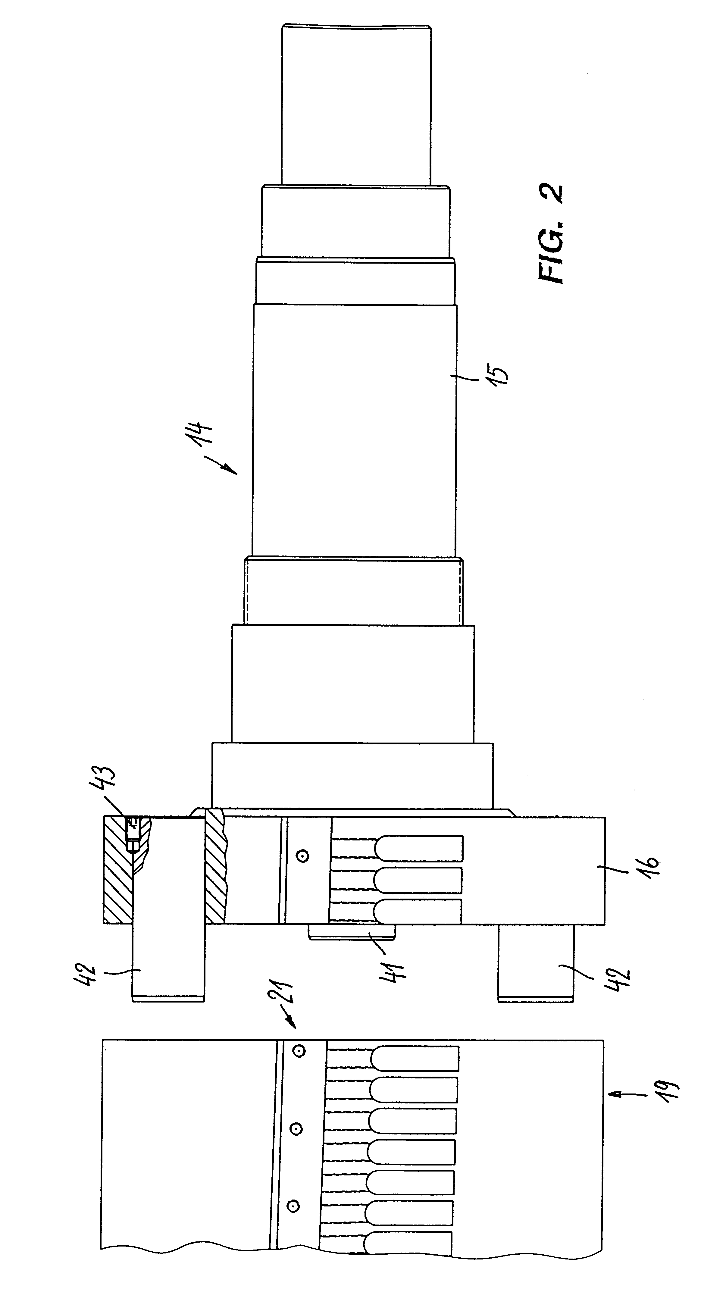
On the shaft end 14 of the cutter shaft 13, which comprises a multistepped journal 15 and a flange 16 in one piece therewith (cf. FIGS. 1 and 2) acts a drive 17, to which belongs a synchronous gear 47, which is fitted in non-rotary manner on the journal. This gear meshes with a corresponding synchronous gear of the cutter shaft cooperating with the cutter shaft 13 shown. Generally synchronous gears are provided on both ends of a cutter shaft. The drive by the drive motors can either take place directly on the shaft journals 15 or by means of the synchronous gear. Generally...


PUM

PropertyMeasurementUnit
web speedaaaaaaaaaa
lengthsaaaaaaaaaa
diameteraaaaaaaaaa

Abstract

A crosscutter for web materials, particularly paper, has a cutter shaft (13), which comprises a light metal cutter block (19) and a steel shaft end (14). The latter comprises a bearing (12) and drive (17)-receiving spigot and a flange (16), which is connected by means of a positive and nonpositive connection to the cutter block. For nonpositive connection purposes threaded bolts (35) are inserted in bushes (33), which are screwed and bonded into corresponding cutter block recesses. In addition, a reamed bolt connection is provided.

Description

The invention relates to a crosscutter for web materials, particularly paper.DE-U-89 00 516 discloses a crosscutter for corrugated paper or board, which has a cutter block in the form of a composite carbon fibre material tube, to which is fitted by means of screws a cutter beam or support. Bearing and driving take place by means of metallic bearing stubs, which are incorporated into the tube.DE-A-195 45 003 discloses a cutter shaft, which has an outer shell of a hollow metal section, particularly aluminium and which passes round an inner shell of a composite fibre material, where the cutter beam is constructed in the outer shell. For bearing and mounting purposes shaft journals are fixed in torsionally and fluxurally stiff manner.In order to be able to cut different formats or sizes with crosscutters and without changing the cutter shaft, it is e.g. known from DE-C-36 08 111 to nonuniformly drive the cutter shafts using unbalance gears or preferably controllable electric motors with...

Claims


Application Information

Patent Timeline
Patent Type & Authority Patents(United States)
IPC IPC(8): B26D7/26B26D1/36B65H35/06
CPCB26D7/2614B26D7/265Y10T83/9464Y10T83/9372Y10T83/4795
Inventor RAU, JURGENKLEIN, HANSJORG
Owner BIELOMATIK LEUZE GMBH & CO
Why Eureka
Try Eureka