
Liner for container

a container and body technology, applied in the field of body lines, can solve the problems of prohibitively expensive to convert existing containers to this configuration, unfavorable container liners, and inability to meet the needs of shipping containers, etc., and achieve the effects of reducing cleaning and fit-out costs, simple fitting, and little training

Inactive Publication Date: 2001-10-30
VISY R & D PTY LTD
View PDF12 Cites 78 Cited by
  • Summary
  • Abstract
  • Description
  • Claims
  • Application Information

AI Technical Summary

Benefits of technology

The liner in accordance with the present invention acts as a physical barrier to rust, paint flakes and other contaminants coming into contact with the cargo. It also acts as a barrier to any condensation that may occur inside the container. The liner is simple to fit and requires very little training to use. The liner can be fitted in less then five minutes and has the potential to reduce cleaning and fit-out costs for food quality containers by up to two-thirds when compared with conventional cleaning and re-fitting. Furthermore, the liner greatly increases the number of containers that may be suitable candidates as food quality containers.
The foldable or hingeable flaps serve two purposes. Firstly, they assist in providing an effective clo

Problems solved by technology

Attempts have been made to provide container liners without commercial success.
This arrangement does not lend itself to shipping containers and requires special clamping means to hold the liner in place.
It would be prohibitively expensive to convert existing containers to this configuration.
It is expensive and each shroud must be designed for a specific tray.
As such it is not commercially attractive.

Method used


Image

  • Liner for container
  • Liner for container
  • Liner for container

Examples


Embodiment Construction

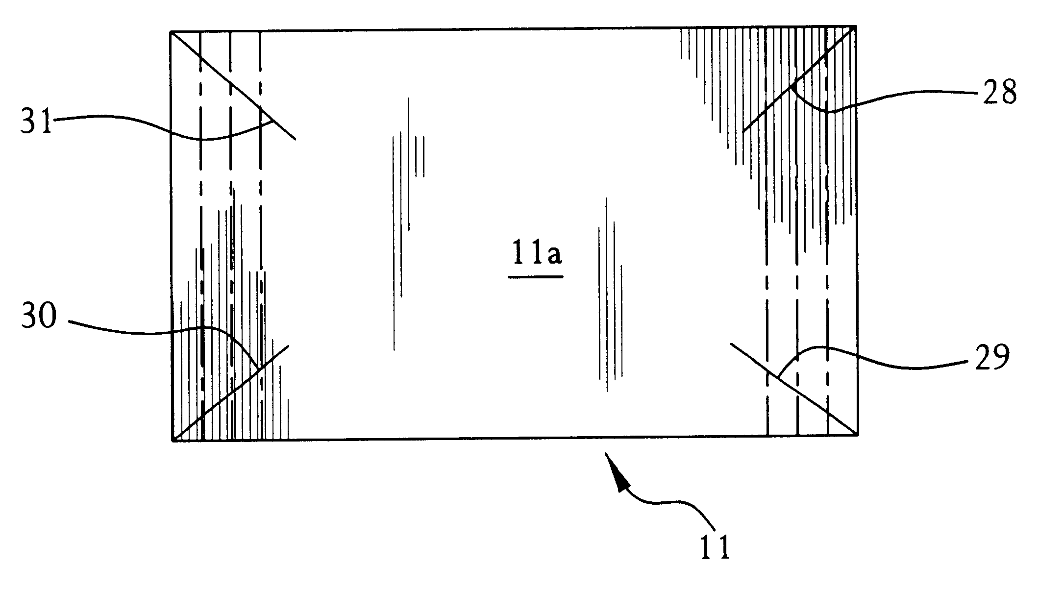
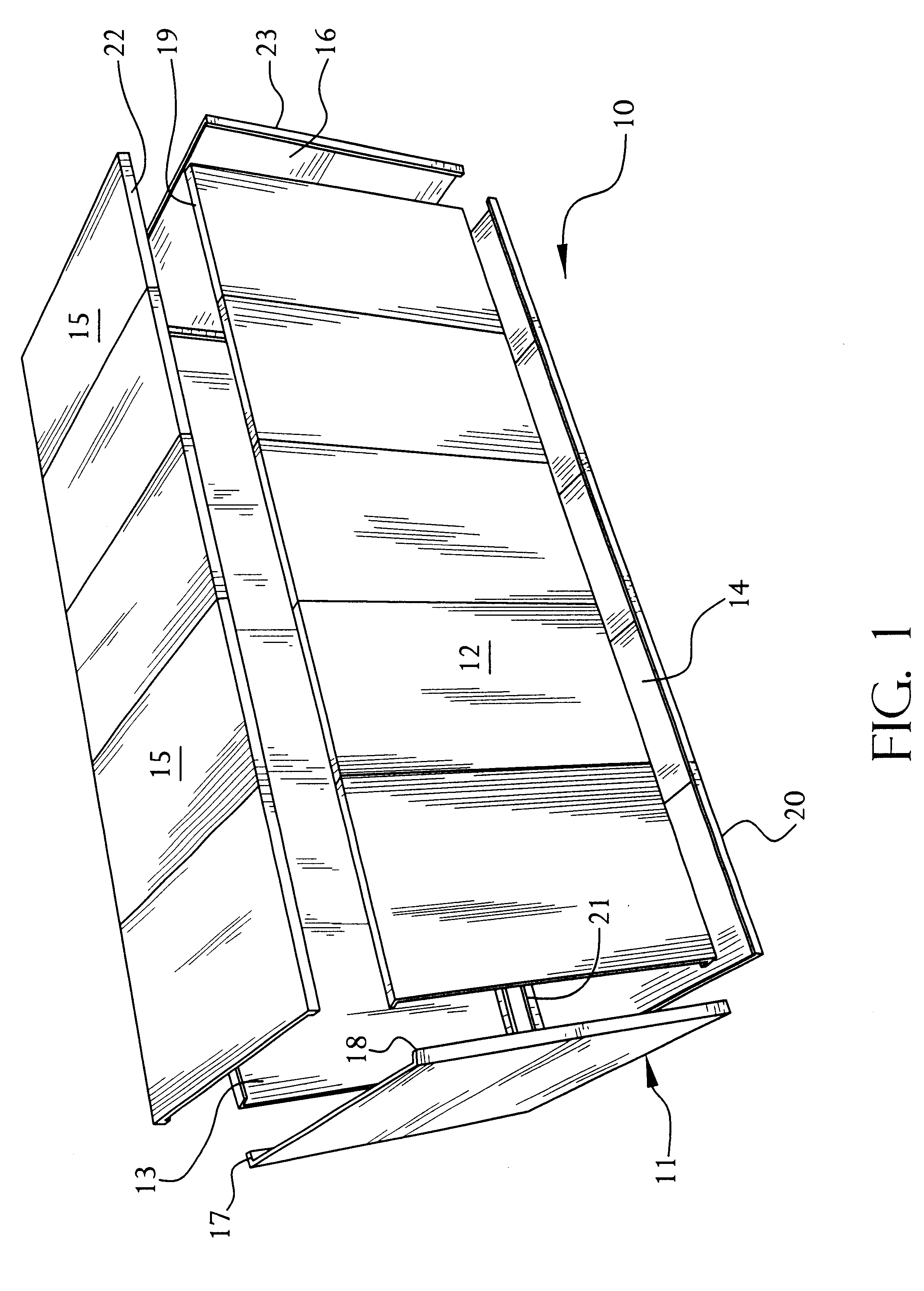
FIG. 1 shows a schematic diagram in accordance with the present invention. The liner 10 includes an end panel 11, a first side wall panel 12, a second side wall panel 13, a floor panel 14, a roof panel 15 and a second end panel 16.

End panel 11 includes flaps 17, 18. End panel 12 includes top flap 19 and a lower flap (not shown). Side wall panel 13 includes similar top and lower flaps to side wall panel 12. Floor panel 14 includes a first flap 20 and a second flap 21. Roof panel 15 includes flap 22 and another flap (not shown) on the edge opposed to the edge carrying flap 22. Second end panel 16 includes flap 23 and another flap (not shown) on the opposed edge to that carrying flap 23.

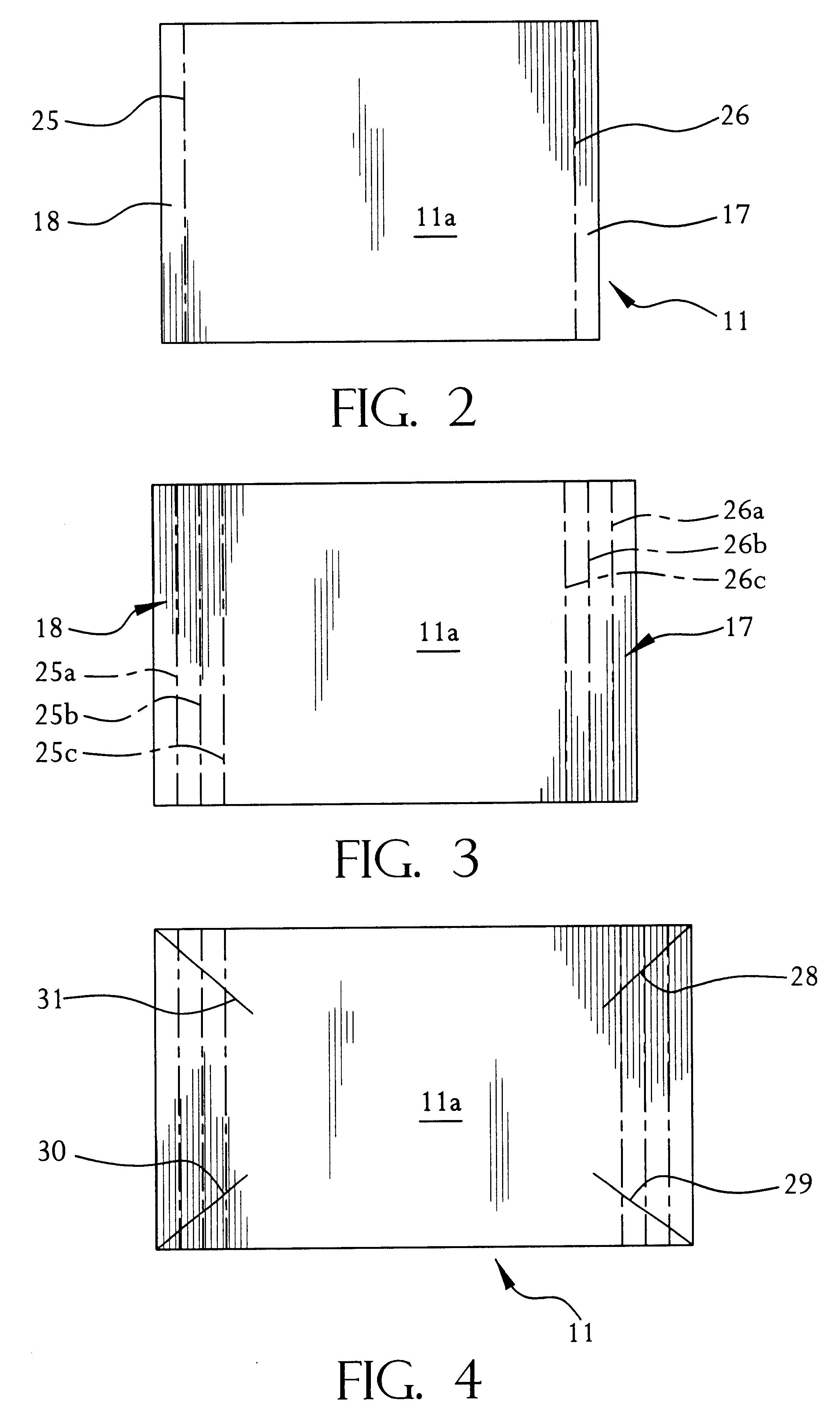
The general configuration of the panels are shown in FIG. 2, which is an end view of end panel 11. As can be seen, end panel 11 includes a main body panel 11a having a first flat 18 and a second flat 17 provided on opposed edges thereof. Panel 11 is manufactured from double faced corrugated paperboard. ...


PUM


Abstract

A liner for a container, such as a shipping container, including an end panel (11), a first side wall panel (12), a second side wall panel (13), a floor panel (14), a roofpanel (15) and a second end panel (16), the end panel (11) including flaps (17), (18), end panel (12) including top flap (19) and a lower flap (not shown) the side wall panel (13) including similar top and lower flaps to side wall panel (12), the floor panel (14) including a first flap (20) and a second flap (21), the roof panel (15) including flap (22) and another flap (not shown) on the edge opposed to the edge carrying flap (22), the second end panel (16) including flap (23) and another flap (not shown) on the opposed edge to that carrying flap (23), the panels (11 to 16) being formed from double faced corrugated paperboard. At least panel (11), and preferably panels (13 to 16), can have multiple fold or score lines (25a to c and 26a to c) to enable folding at selected lines to fit different containers. Diagonal slots (31) can be provided at each corner to accommodate protuberances in the corners of the container.

Description

The present invention relates to a liner for lining a container, such as a shipping container, railway container, trucking container, storage container or transport container. The present invention also relates to a method for lining a container.Produce and goods are frequently stored and transported in large containers. Such large containers typically have inside dimensions of 7'8" (2337 mm) wide, 7'2" (2145 mm) high and 19'4" (5905 mm) long. However, there is no standard dimensions for such containers and in practice there is variation in the dimensions between containers. Furthermore, some containers may be approximately 40' (12.2 m) long. In addition to variations in the internal dimensions of containers, there is also variability in design details of the inner structure of containers, particularly in the corner post region and in the design features along internal edges of the container. Containers are typically made of metal and may have wooden floor installed therein.Such con...

Claims


Application Information

Patent Timeline
IPC IPC(8): B65D81/05B65D5/56
CPCB65D5/566B65D81/05
Inventor COOM, NOELPETERS, GLENN ARTHUR
Owner VISY R & D PTY LTD
Learn More