Protective sleeve for fluid circulation tube

Inactive Publication Date: 2005-10-11
FEDERAL MOGUL SYST PROTECTION GRP SAS
View PDF4 Cites 11 Cited by
  • Summary
  • Abstract
  • Description
  • Claims
  • Application Information

AI Technical Summary

Benefits of technology

[0012]The present invention aims to solve the problems cited hereinabove and proposes a protective sleeve for fluid

Problems solved by technology

Furthermore, it is difficult to fit these tubular sleeves over portions of the pipes that are bent or have different cross sec

Method used


Image

  • Protective sleeve for fluid circulation tube
  • Protective sleeve for fluid circulation tube
  • Protective sleeve for fluid circulation tube

Examples


Embodiment Construction

[0037]A protective sleeve for a fluid circulation tube is described first with reference to FIGS. 1 to 4.

[0038]This type of protective sleeve is generally used for thermally insulating a metal pipe in which a fluid such as automobile vehicle exhaust gas flows.

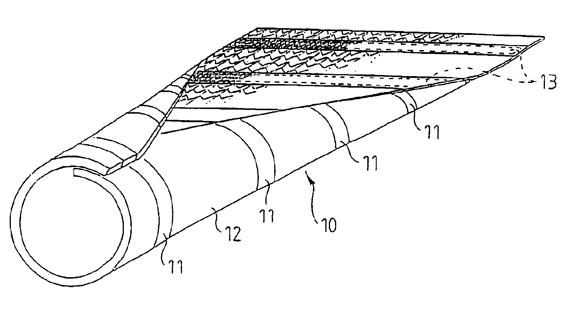
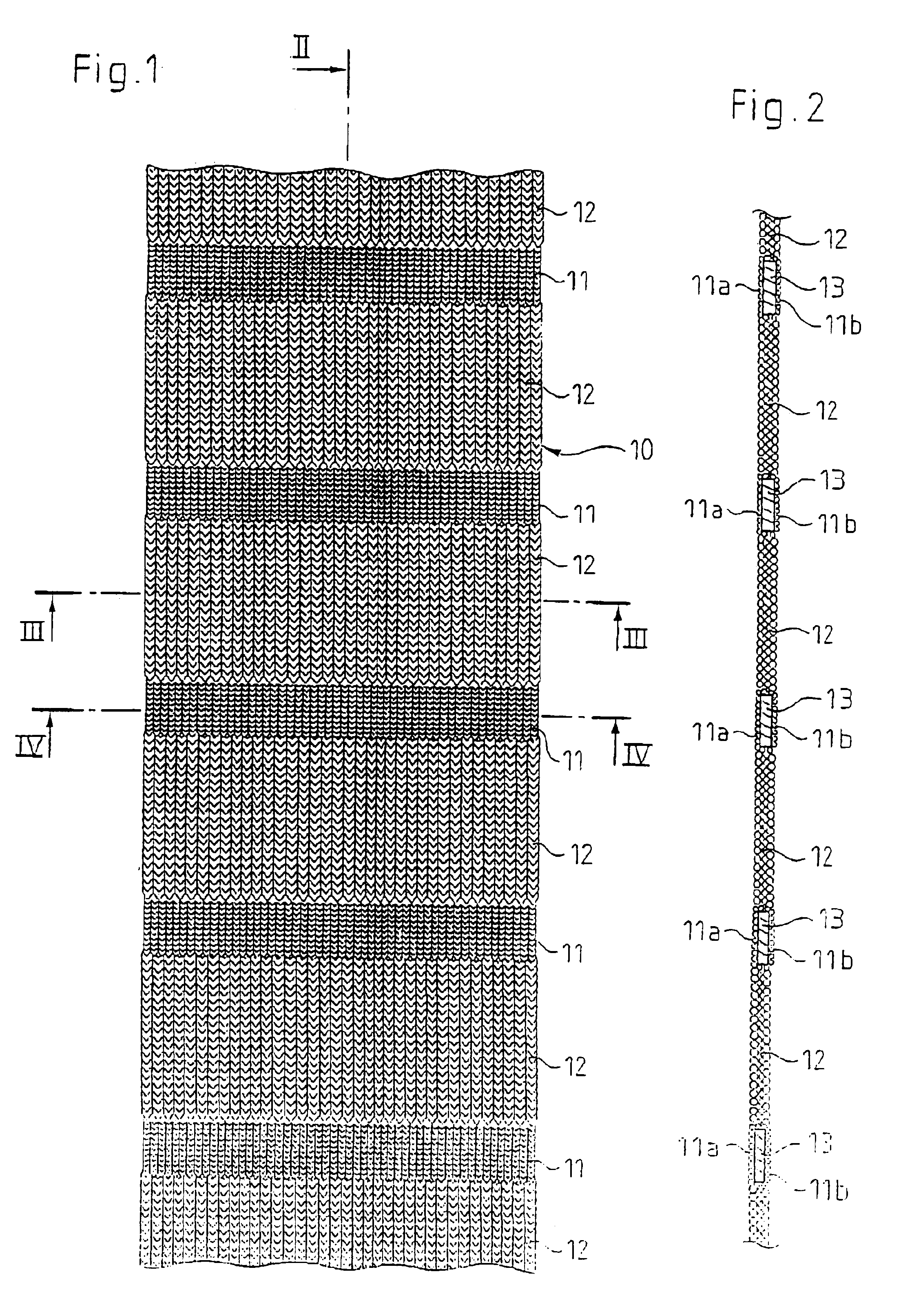
[0039]As shown clearly in FIG. 1, the protective sleeve is made up of a strip 10 of interlaced fibers.

[0040]In this example the fibers are knitted. They could equally be woven or braided to form a strip by interlacing the fibers.

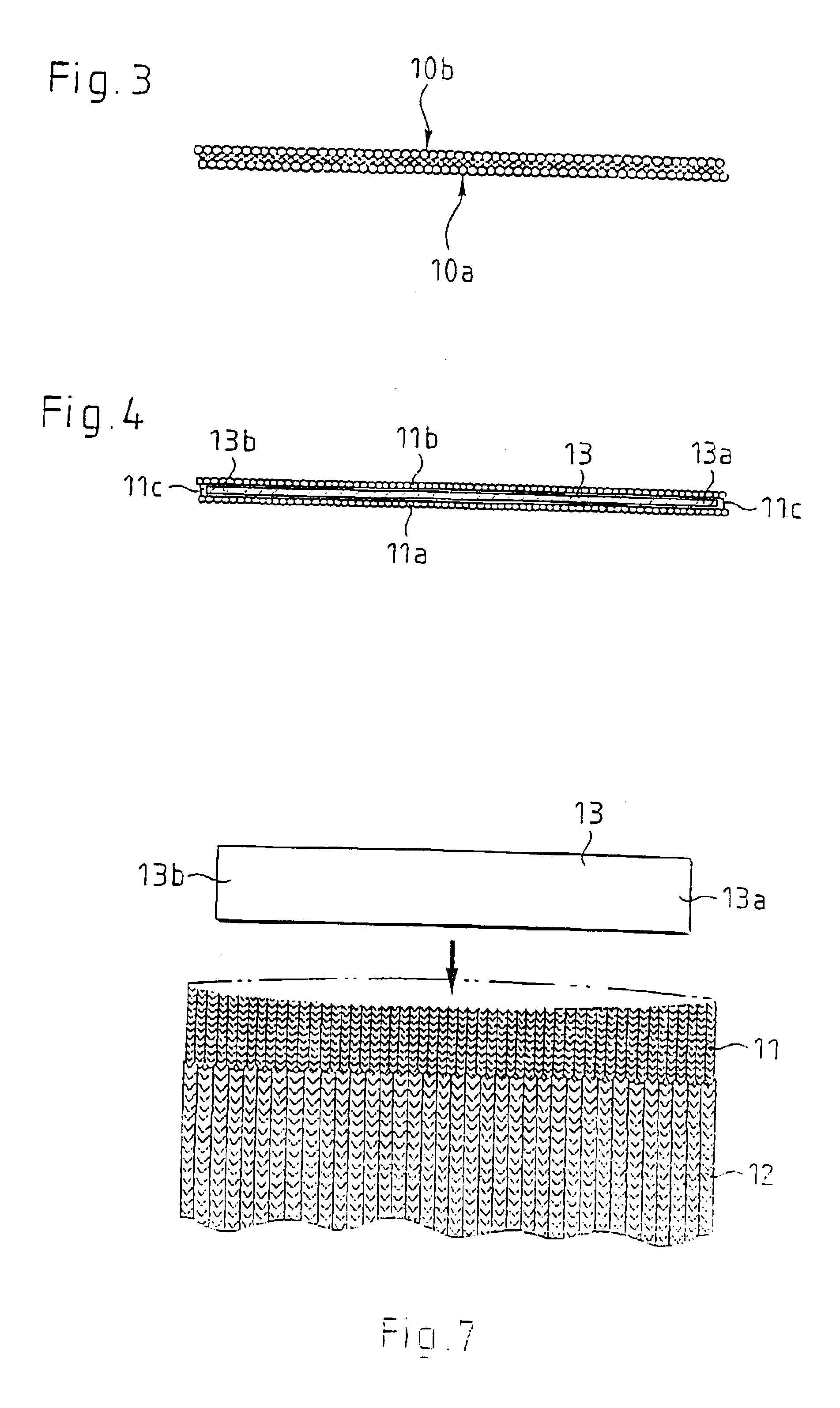
[0041]This strip 10 of fibers comprises at least one pocket 11 extending in the transverse direction of the strip.

[0042]In this example, the strip comprises a plurality of pockets 11 spaced from each other in the longitudinal direction of the strip 10.

[0043]In a nonlimiting manner, the pockets 11 may be equidistant from each other. They could equally be disposed along the strip 10 as a function of the shape of the pipe to be protected.

[0044]In particular, pockets 11 may be disposed in the vicinity of th...


PUM


Abstract

The invention concerns a protective sleeve for fluid circulation tube made of an interwoven fiber structure formed by a strip (10) of interwoven fibers comprising at least a pocket (11) extending in the transverse direction of the strip (10) and including a spring (13) housed in the pocket (11) and designed, in a stable equilibrium position, to maintain the protective sheath closed by overlapping of the longitudinal edges (10c, 10d) of the strip. The invention is useful in particular for thermal protection of an exhaust gas recycling duct in a motor vehicle.

Description

CROSS REFERENCE TO RELATED APPLICATION[0001]This is the 35 USC 371 national stage of PCT / FR02 / 03916 filed on Nov. 15, 2002, which designated the United States of America.FIELD OF THE INVENTION[0002]The present invention relates to a protective sleeve for fluid circulation tubes.[0003]It also relates to a method of fabricating this kind of protective sleeve.BACKGROUND OF THE INVENTION[0004]The general field of the invention is that of thermal protection of fluid pipes used, in particular, on automobile vehicles.[0005]The present invention may be more particularly applied to exhaust gas recirculation (EGR) circuits of an automobile vehicle.[0006]It is important to limit thermal losses from EGR pipes, as much to maintain the recirculated exhaust gas at a satisfactory temperature as to limit heating of surrounding items.[0007]Thermally isolating these pipes by covering them with a braided or knitted sleeve of glass fibers or silica fibers adapted to withstand the high temperatures of th...

Claims


Application Information

Patent Timeline
IPC IPC(8): F01N7/14F16L59/02F02M25/07F02M35/10F01N13/14F16L59/04F16L59/14
CPCF01N13/14F02M25/0714F02M25/0715F02M35/10222F02M35/10334F16L59/021Y02T10/121F01N2510/04F02M26/11F02M26/13
Inventor DELLA PUTTA, LUCIAANDRIEU, HUBERTDROMAIN, LIONEL
Owner FEDERAL MOGUL SYST PROTECTION GRP SAS
Why Eureka
Try Eureka