Sealed, thermally insulated tank with compression-resistant non-conducting elements

a technology of non-conducting elements and seals, which is applied in the direction of floating buildings, liquid dispensing, hull panellings, etc., can solve the problems of high-quality and therefore expensive plywood, complicated manufacture, and use of perlite powder, etc., and achieves the effect of easy adaptability

Inactive Publication Date: 2011-03-08
GAZTRANSPORT & TECHNIGAZ SA
View PDF7 Cites 11 Cited by
  • Summary
  • Abstract
  • Description
  • Claims
  • Application Information

AI Technical Summary

Benefits of technology

[0007]An object of the invention is to propose a tank of this type while also improving at least one of the following characteristics without detriment to others of these characteristics: the tank's cost price, the ability of the walls to withstand pressure and the thermal insulation of the walls. A further object of the invention is to propose a tank of this type in which the non-conducting elements are easily adaptable in terms of their dimensions, without compromising the ability of the walls to withstand pressure and the thermal insulation of the walls.
[0009]Small-cross section pillars of this type have the advantage that they can be distributed in the non-conducting element as a function of local requirements. By adapting the number and the distribution of the load-bearing pillars, the non-conducting element's compression strength can, in particular, be made more uniform than with prior-art spacers. It is also possible to prevent localized depression or pinching of a cover panel. Advantageously, said pillars are regularly distributed over the entire surface of the non-conducting element seen in a plane parallel to the tank wall. A further advantage of the non-conducting element with small-cross section pillars is that it allows the manufacture of a non-conducting element of any desired dimensions without loss of compression strength, at least insofar as these dimensions remain greater than or equal to the spacing between the pillars. A non-conducting element of small surface area may, in particular, be obtained by cutting an element of larger surface area.
[0011]Pillars of this type may have a hollow or solid cross section, for which a number of shapes are possible. Preferably, said pillars have a closed hollow transverse section. Such hollow pillars with a closed transverse section, in particular tubes with a circular cross section, make it possible to obtain very good anti-buckling resistance while at the same time minimizing the effective thermal conduction cross section.
[0022]A load-bearing structure of this type formed as a single piece combines very advantageous mechanical properties both in terms of stiffness and in terms of anti-buckling resistance in the direction of the thickness of the hollow elements, of ease of forming, of thermal insulation and of cost price. Indeed, for a given geometry of the pillars, their anti-buckling resistance is increased by the rigid integral links as compared to separate pillars. Furthermore, manufacture of the links between the pillars and pillars, i.e. at least one portion of their height, in the form of a single piece makes it possible to dispense with certain assembly operations, makes it possible to obtain a relatively rigid load-bearing structure without excessively increasing the cross section of the pillars and / or their thickness, and thus the thermal bridges, and simplifies fitting of the thermal insulation liner in the non-conducting element.
[0026]Advantageously, an insulation piece having a thermal conductivity that is lower than that of said pillars is interposed, on each occasion, between the two assembled pillars. This makes it possible to improve the thermal insulation obtained by means of the non-conducting element.
[0031]According to a preferred embodiment, said thermal insulation liner includes reinforced or unreinforced, rigid or flexible foam of low density, i.e. under 60 kg / m3, for example around 40 to 50 kg / m3, which has very good thermal properties. It is also possible to use a material of nanoscale porosity of the aerogel type. A material of the aerogel type is a low-density solid material with an extremely fine and highly porous structure, possibly with a porosity up to 99%. The pore size of these materials is typically in the range between 10 and 20 nanometers. The nanoscale structure of these materials greatly limits the mean free path of the gas molecules, and therefore also convective heat and mass transfer. Aerogels are thus very good thermal insulators, with a thermal conductivity, for example, below 20×10−3 W·m−1·K−1, preferably less than 16×10−3 W·m·−1·K−1. They typically have a thermal conductivity 2 to 4 times as low as that of other, conventional insulators, such as foams. Aerogels may be in different forms, for example in the form of powder, beads, nonwoven fibers, fabric, etc. The very good insulating properties of these materials make it possible to reduce the thickness of the insulating barriers in which they are used, which increases the useful volume of the tank.

Problems solved by technology

Furthermore, the use of a powder such as perlite complicates the manufacture of the caissons because the powder produces dust.
Thus, it is necessary to use high-quality and therefore expensive plywood so that the caisson is well sealed against dust, i.e. knot-free plywood.
All these operations complicate manufacture and increase the cost of the caissons.
Moreover, if the thickness of the insulating caissons is increased with an insulating barrier, the risk of the walls of the caissons and the load-bearing spacers buckling increases considerably.
Furthermore, if the thickness of the caissons is increased it is observed that, inside the caissons, gas convection currents arise that are highly detrimental to good thermal insulation.
Although the result of this is a good compromise in terms of anti-buckling strength and thermal insulation, it has to be admitted that this manufacturing process also requires numerous assembly stages.

Method used


Image

  • Sealed, thermally insulated tank with compression-resistant non-conducting elements
  • Sealed, thermally insulated tank with compression-resistant non-conducting elements
  • Sealed, thermally insulated tank with compression-resistant non-conducting elements

Examples


Embodiment Construction

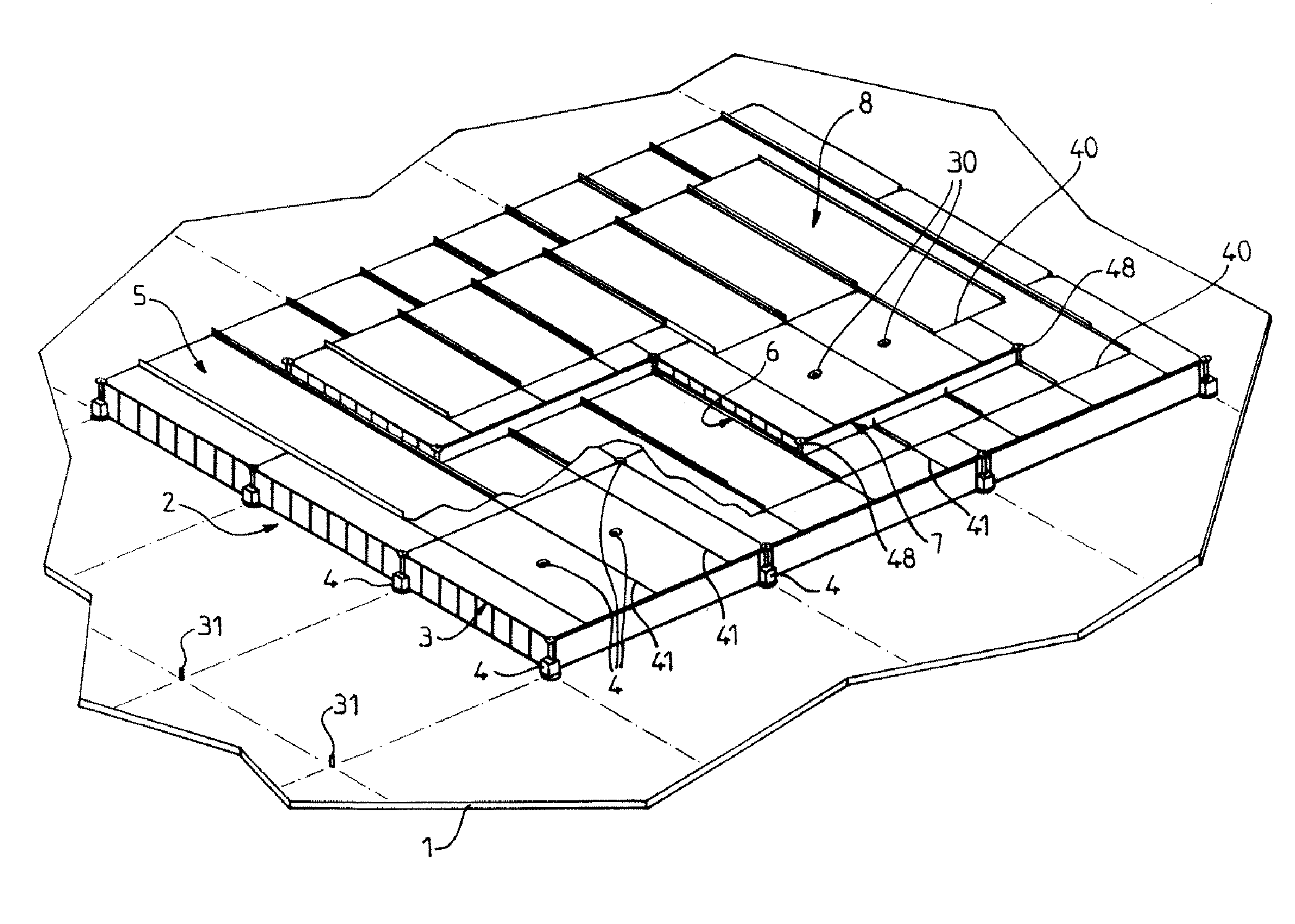
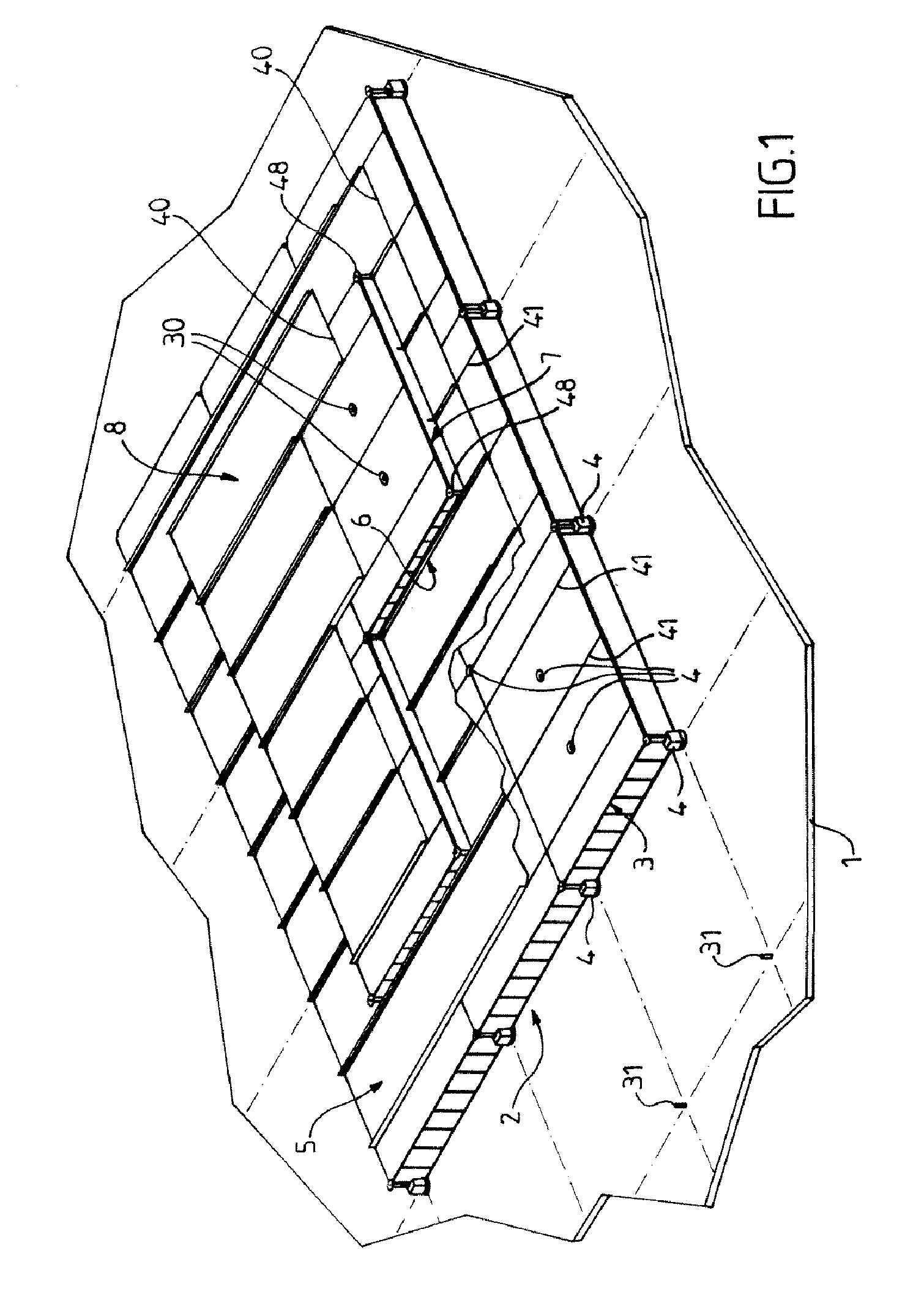
[0051]A description will be given below of several embodiments of a sealed, thermally insulated tank incorporated in and anchored to the double hull of a structure of the FPSO or FSRU type or of a methane-type carrier. The general structure of such a tank is well known per se and has a polyhedral form. Therefore, a description will be given only of a wall zone of the tank, it being understood that all the walls of the tank have a similar structure.

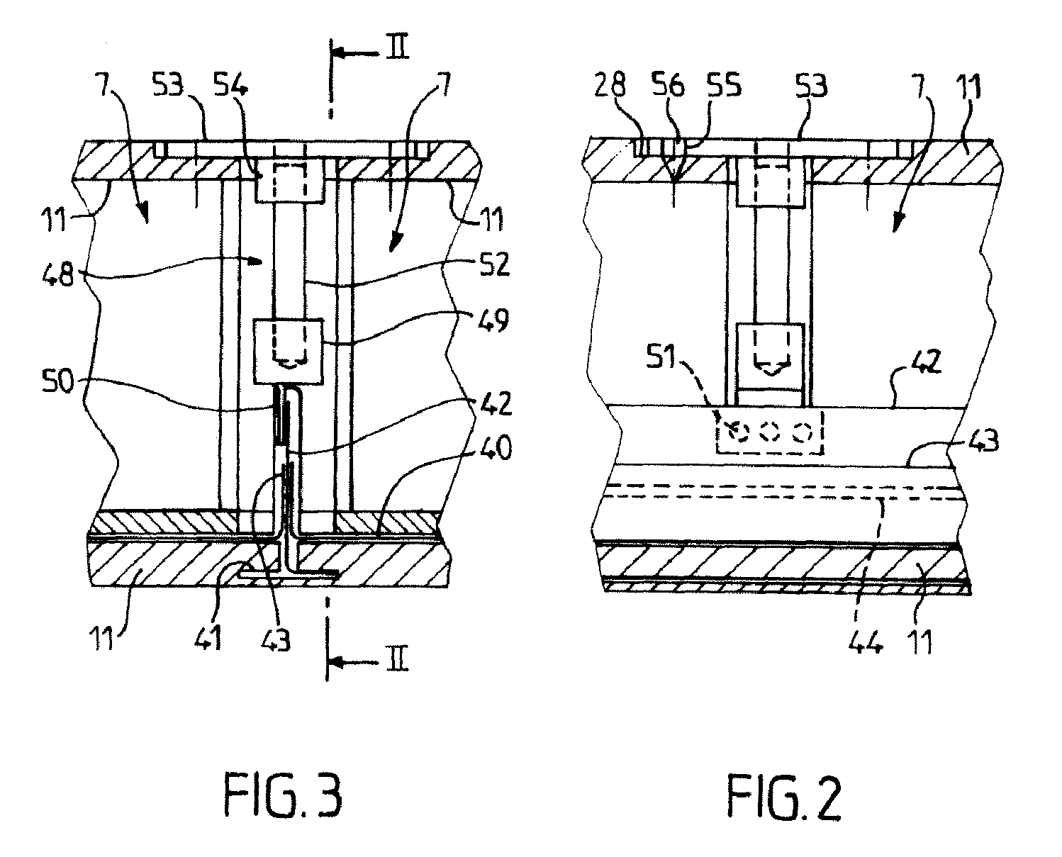
[0052]A description is now given of a general embodiment that is useful for understanding the invention, with reference to FIGS. 1 to 3. FIG. 1 shows a zone of the double hull of the ship, denoted by 1. The tank wall is composed, in succession, in its thickness, of a secondary insulating barrier 2 formed from caissons 3 juxtaposed on the double hull 1 and anchored to the latter by means of secondary retention members 4, then a secondary sealing barrier 5 carried by the caissons 3, then a primary insulating barrier 6 formed from juxtaposed ...


PUM


Abstract

Sealed, thermally insulated tank has tank walls fixed to the load-bearing structure (1) of a floating structure, the tank walls having, in succession, in the direction of the thickness from the inside to the outside of the tank, a primary sealing barrier (8), a primary insulating barrier (6), a secondary sealing barrier (5) and a secondary insulating barrier (2), at least one of the insulating barriers includes juxtaposed non-conducting elements, each non-conducting element including a thermal insulation liner (63) and load-bearing elements that rise through the thickness of the thermal insulation liner in order to take up the compression forces, characterized in that the load-bearing elements of a non-conducting element include pillars (65) of small transverse section as compared to the dimensions of the non-conducting element in a plane parallel to the tank wall.

Description

CROSS REFERENCE TO RELATED APPLICATIONS[0001]This application is a continuation of co-pending application Ser. No. 11 / 265,079 filed on Nov. 3, 2005, which claims priority to French Application No. 04 11968 filed on Nov. 10, 2004. The entire contents of each of the above-identified applications are hereby incorporated by reference.BACKGROUND OF THE INVENTION[0002]The present invention relates to the production of sealed, thermally insulated tanks consisting of tank walls fixed to the load-bearing structure of a floating structure suitable for the production, storage, loading, ocean carriage and / or unloading of cold liquids such as liquefied gases, particularly those with a high methane content. The present invention also relates to a methane carrier provided with a tank of this type.DESCRIPTION OF THE RELATED ART[0003]Ocean carriage of liquefied gas at very low temperature involves an evaporation rate per day's sailing that it would be advantageous to minimize, which means that the t...

Claims


Application Information

Patent Timeline
Patent Type & Authority Patents(United States)
IPC IPC(8): F17C1/00
CPCB63B25/16F17C3/027F17C2203/0358F17C2203/0631F17C2221/033F17C2223/0161F17C2223/033F17C2270/0107Y10S220/901F17C2203/0325B63B3/68
Inventor DHELLEMMES, JACQUESMICHALSKI, PIERREFARGANT, VINCENT
Owner GAZTRANSPORT & TECHNIGAZ SA
Why Eureka
Try Eureka